This thread has been locked.

If you have a related question, please click the "Ask a related question" button in the top right corner. The newly created question will be automatically linked to this question.

TIDM-1000: No-load to full load sudden transient

Part Number: TIDM-1000
Other Parts Discussed in Thread: SFRA

Dear Team,

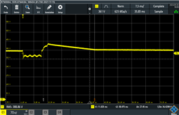
           We are facing two kind of issues, One is at no-load and 25W load condition the output voltage is not regulating (we need the output voltage to regulate at 380V instead it was generating 420V) and the second was, while introducing the load of 1000W suddenly from no-load the output voltage drops to 320 and starts to rise and  gets stabled in 370 instead of 380V, so to solve this problems we change the "VIENNA_GV_PI_MIN" Value from -0.02 to -0.1, Which have solve our problem for 25W load but making the second problem even worse(when introduce the sudden load of 1000W the output voltage drops to 320V and stables at 340V

So can you please suggest something regards this problems and how this Kp, Ki gain MIN and MAX values were calculated, How these values are going to affect the systems output.

  • Hi Manoj,

    You need to stablize the PI loop for both voltage and currents here. 

    In the first case, during light load (25W), the change of Gv has helped, but this might not be enough for 1000W step change, as a result your loop response is bad. Can you try tuning current loop (Gi) also at 1000W and input those parameters to control loop. In my opinion, the control parameters used in the exsiting design should be able to support this at 1kW. 

    Queries:

    1. I assume you are using build 4? 

    2. Have you enabled Non-linear voltage loop here?

    3. Is this test done on TIDM1000 or your own hardware?

    4. I see the transient response is bad from the image you shared. I think tuning the current control should help.

    Best Regards,

    Uttam

  • Hi Uttham,

    Thank you for your response

    1.  assume you are using build 4? 

      We are using  Build 3. Could you please suggest how build 4 is can be the problem of our issue?

    2. Have you enabled Non-linear voltage loop here?

    Yes , we are using the Variable Kp Value in Code.

    3. Is this test done on TIDM1000 or your own hardware?

    We are testing on our hardware.

    Could please suggest how we can tune the Ki Constant for Current loop Compensator?

    Thanks

    Manoj

  • Hi Manoj,

    with build 4/build 3 it shouldn't be a problem. As this has non-linear Ki enabled for both, it should withhold the change in the load step. Not sure why this has been not working at your end. Can you try below:

    1. do the SFRA comparision (with your parameters) at both light load and full load to see the plots are ok with open loop (plant model) & closed loop (OL model).

    2. If not adjust, tuning parameters for both voltage (Kv) and current (Ki) using design compensator following the procedure on build 1 and build 2, then move to build 3. 

    Please refer design guide for SFRA and design compensator usage. 

    Alternatively, 

    with your existing parameters, try to increase your non-linear Kp value and observe the step load to see any betterment.

    Best Regards,

    Uttam Reddy