TMS320F280039-Q1: C2000 microcontrollers forum

Part Number: TMS320F280039-Q1

Tool/software:

Hi Champ,

   How we get the data for  Figure 6-21 Negative Resistance Variation at 10 MHz, by testing on EVM board?

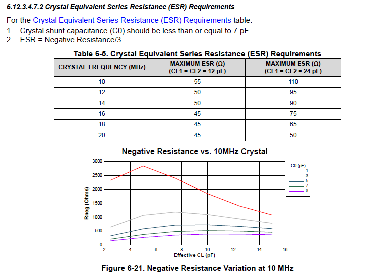
From the datasheet, in 10MHz case , the maximum ESR is form 55 to 110.

ESR = Negative Resistance/3,

in case the effective CL from 6-12pF, C0 = 1-7pfF. the Negative Resistance is very large >500Ohm, but from datasheet, the generally accepted practice is to have Rneg > 3x ESR to 5x ESR to ensure the crystal starts up under all conditions.

How to understand above  Figure 6-21?

  • Hello Huihuang,

    The subject matter expert is OOO.

    I believe this evaluation was done with MCU using internal boards (VDB's) not  on EVM. I can check internally on figure 6.21 specifically. 

    But if you are using 10MHz crystal as long as its ESR is within the requirements it should be good. 

    Regards,

    Uttam

  • Any update on this post?

  • Hi Johnson,

    The negative resistance curves were taken from design simulation results as it is impractical to measure this on all the combinations of CL and CO.

    Regards,

    Joseph

  • Hi Joseph,

    In case the effective CL from 6-12pF, C0 = 1-7pfF. the Negative Resistance is very large >500Ohm, but from datasheet, the generally accepted practice is to have Rneg > 3x ESR to 5x ESR to ensure the crystal starts up under all conditions.

    How to understand the picture?

  • Hi Johnson,

    Take for instance the case of 10MHz crystal where max ESR is 55 ohms in table 6-8, 3x to 5x is 165ohms to 275ohms for negative resistance criteria.  This means that negative resistance above 165 to 275 ohms will not have issues with start up so 500 ohms or higher negative resistance will not have any issues.

    Hope this is clear.

    Regards,

    Joseph

  • Hi Joseph,

    if like this, why the Rneg is  > 3x ESR to 5x ESR, why we not say Rneg is  > 3x ESR or >5x ESR?

    Did you means the figure 6-21 is the maximum acceptable negative resistance value?

  • Hi Johnson,

    Please note that the plots were provided from simulation as a guideline for choosing the crystal given C0, CL and ESR.  Negative resistance is produced by the oscillator circuit to counter the impedance presented by the crystal,  A higher negative resistance means it should be able to provide enough energy to start oscillation for the resistive part of the crystal, C0 and CL.  >3x to >5x of ESR is a general criteria for negative resistance.  This is the first part.  The second part is to characterize the crystal to make sure that whatever part with given ESR, C0 and CL will actually start up and sustain oscillation.

    Regards,

    Joseph  

  • Hi Johnson,

    I understand the second part.

    But is till don't understand the means of figure 6-21, Did you means the figure 6-21 is the maximum acceptable negative resistance value?

  • Hi Johnson,

    You can interpret it that way and following example might better illustrate this.  Use the graph as a guide for an indication if the crstal of choice meets the 3X to 5x criteria to start an oscillation.  For example, take 10MHz crystals both having C0=5pF and CL1=CL2=24pf (effective CL of 12pF).  The first crystal has max ESR of 100 ohms.  The second crystal has max ESR of 1750ohms.

    Based from the graph, the crystal circuit provides a negative resistance (to counter the XTAL effective impedance of  ESR) of around 700ohms for a C0 of 5pF and CL effective of 12pF.  The general criteria for a possible start up is to have negative resistance of that is greater than 3X to 5X of ESR.  For the first crystal, negative resistance requirement is 3x90 to 5x90 or 270ohms to 450ohms.  The second crystal needs to have at least 3x175 to 5x100 or 525ohms to 800ohms negative resistance.  Based on these calculations, I will choose the first crystal as it meets the criteria for the negative resistance where 270ohm to 450ohms is well within the 700ohms negative resistance that the oscillator circuit provides.  The second crystal's negative resistance requirement in outside the range of what the oscillator circuit can provide (525ohms to 800ohms is marginal to the 700ohms negative resistance provided by the circuit).

    Regards,

    Joseph