This thread has been locked.

If you have a related question, please click the "Ask a related question" button in the top right corner. The newly created question will be automatically linked to this question.

LAUNCHXL-F280049C: ADC samples of diffrent quality, phase currents.

Part Number: LAUNCHXL-F280049C
Other Parts Discussed in Thread: AMC3301, TLV9064

Tool/software:

Hello,

I am developing a AC motor controller, when i measure the three phase currents they are differing alot in quality.

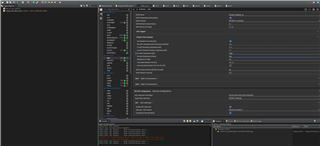
I am using these ADC settings, PWM4 triggers SOCA on ADC_A, B & C.

Only interrupt on ADC_B (PHASE W SOC0) End of conversion.

at ADC interrupt i get all results and pass them to a datalogger array of size 512.

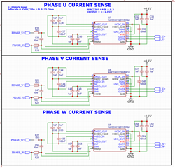
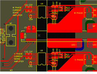
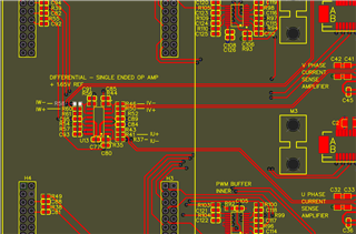
Signals getting converted are from AMC3301, layout and shematic are identical

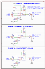
diff to singel ended conversion

Any help is appreciated in helping me smooth this out, W phase looks worst.

  • You can run the motor with open loop and use an oscilloscope to check if the output signals of the amplifier and the input signals of the ADC are good? If not, you have to check if there are something wrong on the schematic and PCB layout design. If the signals are right, and then check if the ADC configuration is correct.

  • I am currently only in the open loop phase, and i dont really know what to look for with my scope, i am probing the input pin of the adc, but i cant really tell any bigger difference.

    Could anyone take a look if the signal chain looks ok for  the AMC3301 and TLV9064?

    in the test i was running the speed was 35Hz with a dc positive and negative of 24V (48V total) each, approx drawing 200mA, 100 per half dc link.

  • You can use PWMDAC or on-chip DAC to verify if the current and voltage are sensing correctly. As you mentioned above, you should run the motor with open-loop first. Seems like the schematic is good since the other two phases sensing signals are correct, you have to check the PCB layout and verify the ADC configuration by yourself.