


Tool/software:
Hello Experts,
We are trying to establish what are the correct Id, Iq wave forms should look like if the system is stable on our custom inverter hardware. We are running a FW derieved from the sensored dual axis drive project built in speed loop.
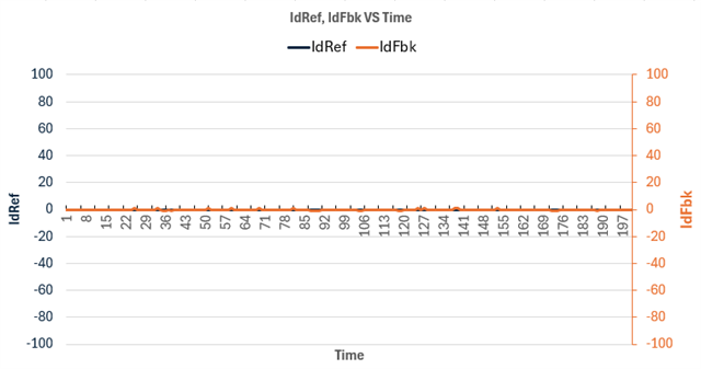
Firstly , If the system is stable, and if the Id reference(IdRef) is set to zero, it is asumed that Id feedback(IdFbk) which is calculated from the clarke transformations should also be 0 , Vd is allowed to move around so that Id feedback comes to 0. --> Is this statement correct?
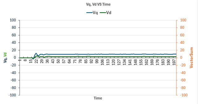
In our code , We limit Vq(pi_iq.out) to 0.91 and Vd to 0.3 (pi_id.out) .The vector sum of Vd and Vq is less than 1. We have captured some data using some circular buffers at regular intervals.
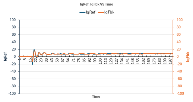
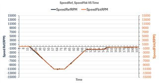
This is the wave form that we are getting if we run the motor at 1000 RPM at no load, note that the values of Id,Iq,Vd and Vq are all in (pu * 100)
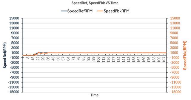
Now when we increase the speed to 11000 RPM, we notice that Id feedback is no longer near 0, is this normal?,
We also provide a torque from +2 Nm to -15Nm). It goes from an oposing torque to a regenerative torque.
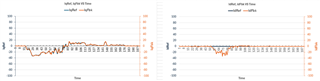
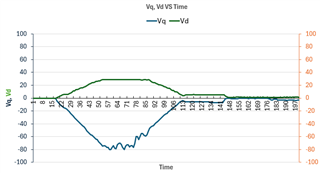
Notice that Id feedback is no longer 0? Does this happen because Vd is not allowed to increase further? [> 0.30, (> 30 in the graph)]
How do we ensure that the Id feedback current is closes to 0 as possible even at higher speeds.
We also noticed that as the load is increased Id increases correspondingly!
