This thread has been locked.

If you have a related question, please click the "Ask a related question" button in the top right corner. The newly created question will be automatically linked to this question.

TMS320F28035-EP: TMS320F28035

Part Number: TMS320F28035-EP

Tool/software:

Hello everyone,

I am trying to code my string MPPT boost converter. Nevertheless, I am having difficulty to read the value from ADC and I am getting the follwing error. But there is no problem in tuning while I work with TI reference design. Can anybody help me to resolve this error?

C28xx: Trouble Halting Target CPU: (Error -154 @ 0x0) One of the FTDI driver functions used to write data returned bad status or an error. (Emulation package 9.10.0.00080)

C28xx: Unable to determine target status after 20 attempts

C28xx: Failed to remove the debug state from the target before disconnecting.  There may still be breakpoint op-codes embedded in program memory.  It is recommended that you reset the emulator before you connect and reload your program before you continue debugging

The error comes only when I turn on power stage. Plus, the CCS gets startled to read any instuctions, including a muse click. After referring the CCS forum, I installed all the drivers for emultion package recommended form TI website; but was not succesfull. Having suspected the EMI issue, the controller is completely isolated with EMI tape, still couldnt be succesfull, can anyone help me out here?

Once I turn on Power stage, all my serial ports are having some commincation issues, because, the wireless mouse even gets non-operatable while I turn on. Just thought of sharing this, in case it could give some suggestion. 

Many thanks,

Dr.Ram

  • Hi,

    The error comes only when I turn on power stage. Plus, the CCS gets startled to read any instuctions, including a muse click. After referring the CCS forum, I installed all the drivers for emultion package recommended form TI website; but was not succesfull. Having suspected the EMI issue, the controller is completely isolated with EMI tape, still couldnt be succesfull, can anyone help me out here?

    Do you have an oscilloscope so that you can watch the communication signals? 

    It sounds like this is a big EMI noise problem. That would help confirm this suspicion.  

    Best Regards,

    Ben Collier

  • Hello Expert Mr.Benjamin Collier,

    Thanks a lot for helping me out, may I know, what signals you want to check? This would help me to find the issue.

    Also, I would ike to ask you that, we have just used an capacitor to isolate controller ground between power stage ground, and control signals. So, do you think that not using a seperate isolator could also be an issue here? 

    Many thanks

    Ram 

  • Ram,

    Sorry, I meant to ask for you to check the JTAG signals. TMS, TCK, TDI, TDO and TRST.

    So, do you think that not using a seperate isolator could also be an issue here? 

    Are controller ground and power stage ground connected in any way other than this capacitor? So are they effectively disconnected for DC? 

    I don't think this would cause the issue that you're seeing above, but I'm not sure if this would cause any other issue.

    Best Regards,

    Ben Collier

  • Dear Mr.Benjamin, 

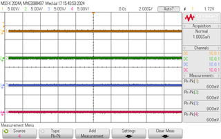
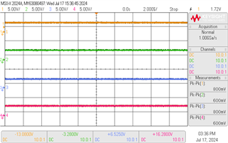
    Please find the waveform attached herewith, these waveforms are taken while power stage is off. From evalautions, I wasnt able to see 3.3V in any of the pins (TMS, TCK, TDI, TDO and TRST) -Image 1. But then, for the same code on TI reference design, I could able to see 3.3 V (Image 2).

    I seek your sinciere advice in this regard. 

    Ram

  • Ram,

    Please find the waveform attached herewith, these waveforms are taken while power stage is off. From evalautions, I wasnt able to see 3.3V in any of the pins (TMS, TCK, TDI, TDO and TRST) -Image 1.

    Is the F28035 device powered on at this point? 

    But then, for the same code on TI reference design, I could able to see 3.3 V (Image 2).

    The TI reference design will have pullup resistors on these signals (pulldown on TRST). There should even be internal pullup resistors on these pins. I am surprised that you are seeing them tied low unless the device is now powered on.

    Anyway, I wanted to see if there was noise at the point that you lose communication, which would be after the power stage is turned on.

    Best Regards,

    Ben Collier

  • Dear Expert Mr.Benjamin, 

    thanks a lot for explaining the difference between TI reference design and customised converter design. Indeed, it was a new knowledge for me. 

    The TI reference design will have pullup resistors on these signals (pulldown on TRST). There should even be internal pullup resistors on these pins. I am surprised that you are seeing them tied low unless the device is now powered on.

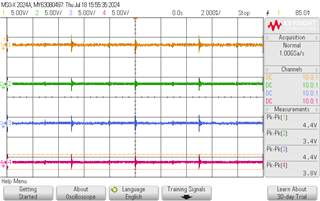
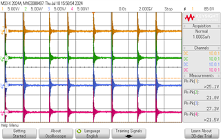
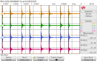
    As you suspected there is a huge noise in the JTAG pins. The converter is designed for 12 A, and untill 0.5 A, the noise in JTAG is minimal, Please refer image 1. Rising the current to 1 A creates a huge noise in JTAG (please refer image 2). Would like to hear from you for the suggestion.

    Many thanks,

    Ram

  • Ram,

    Is this noise present in the TI reference design? If not, I can only recommend that your PCB is redesigned to more closely follow the TI reference design so that this noise is not present in the JTAG signals.

    Honestly, this noise could disrupt many functions of the C2000 device, and possibly damage the device.

    Best Regards,

    Ben Collier