This thread has been locked.

If you have a related question, please click the "Ask a related question" button in the top right corner. The newly created question will be automatically linked to this question.

TPS65219EVM-SKT: The nSTROUT blinks endlessly

Part Number: TPS65219EVM-SKT
Other Parts Discussed in Thread: TPS65219EVM

Tool/software:

Hello, i have a problem with the TPS65219EVM-SKT, we also have the eval kit. I don't know in which forum i should post this issue, so please tell me if the one i choose is incorrect.

So about the problem, we sucessfully configured the voltages with the GUI, without load

But when we add resistors on Vbuck 1 0.44 Ohm with 0.85V and Vbuck 2 0.66 Ohm with 1.1V, and we turn on the alimentation.

The nSTROUT blinks endlessly, and the nINT led turns red, probably meaning theres an error, i don't know why it does that, as we do not overcharge the component.

We also don't give more Ampers than the limit the component can withstand.

  • Hi,

    Thank You for using E2E. It is recommended to use the TPS65219EVM (soldered down EVM) when loading the rails to test the device performance. TPS65219EVM-SKT is only used for NVM programming and basic output voltages/sequence checks. It has a low cost open top-through hole socket with high parasitic and a non-ideal layout which doesn't represent the real use case. Additionally we found a logic bug in the circuitry that drives the nINT and nRSTOUT LEDs. This bug only affects TPS65219EVM-SKT and not not impact the PMIC behavior.

    Could you try re-programming the PMIC on the TPS65219EVM with the custom NVM configuration (and load on each Buck) nd let us know if there are any issues?

    Thanks,

    Brenda

  • Hello, sorry for the late reply, we were busy with other matters.

    Isn't the TPS65219EVM the microcontroller itself, or another model, if so, does that mean we have to order it? we already paid 200€. We used the TPS65219-GUI to configure it, and everything worked fine. Apart from the problem we said in the first post.
     
    And my bad, the model we use is the TPS65219EVM-RSM Evaluation module, does that change anything? Sorry for all the questions, it's the first time we use a TI PMIC.

    Thank you for the reply, 
    Esteban

  • Hi Esteban,

    If you are using TPS65219EVM-RSM, then there shouldn't be any issues with the logic that drives the LEDs. However since it also uses a socket, the same concerns about loading the rails and the parasitic are applicable. 

    If you send us the custom NVM (in CSV format), we can help with the review and provide feedback about the correct jumper configuration in the EVM. Here are the instructions to generate the NVM config file with the GUI: File --> Register File Format --> select CSV --> click on "Save Registers As.."

    Thanks,

    Brenda

  • regs_conf.csv

    Hello Brenda, Thank you for your reply.

    Here's the custom NVM in CSV format. It's the one we use. Tell me if that is correct.

    Thanks,
    Esteban

  • Could you also provide a picture of the TPS65219EVM-RSM so we can review the jumper configuration?

    In the meantime, here are a few observations noticed on the NVM config:

    • two digitals pins are configured as "MODE". Consider changing the MODE/RESET config as "RESET".

    • Which processor or SoC are you planning to power with the custom NVM config? I recommend reviewing the configuration of the power-up sequence. nRSTOUT is currently configured to be released at the beginning of the sequence which is not common. 

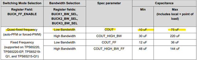
    • Just for reference, the table below shows the required output capacitance on each buck based on the badwidth config. Your current NVM configuration has all the Bucks configured as quasi-fixed frequency and low bandwidth.

    Thanks,

    Brenda

  • Hello Brenda,
    Here is a picture, and thank you for the different observations.

    For precision :
    * EXTPWR cable goes to the power supply (which is 3.3V), the GND of it to the GND of the power supply.
    * VBUCK1 goes to an precision multimeter, and it pass through resistors (with the Ohm value i said in the first post), then go back to the VBUCK1 GND.
    * VBUCK2 only have resistors on it. (for a total of the value i said in the first post too)

    Thanks, 
    Esteban.

  • Hi Esteban,

    The jumper config looks correct. Could you run the test described below and let me know if it works? 

    • Disconnect any external load from ALL the PMIC rails.
    • change the VSYS jumper (J1) to use "5VUSB" instead of EXTPWR.
    • refresh the GUI website
    • connect the PCB to the PC
    • turn ON the S1 switch (button left of PCB)
    • measure output voltages on each PMIC rail and let me know if you still see the same behavior.  

    Thanks,

    Brenda

  • Hello Brenda,
    All the voltages we set in the GUI works just fine without resistors, we have the correct values when we measure the output voltage,

    I also did change VBUCK1 and VBUCK2 to high bandwidth to see if it fixes it (the main problem) but to no avail, and i set the RESET MODE to RESET too.
    It's when we put the resistors on, and then turning on the S1 switch that there's the nRSTOUT and nINT problem mentionned before, even if we do not use more ampers than the component limit.
    Another thing is that when we use resistors on only one VBUCK it works fine too, but its when we add them to the second VBUCK that the problem occurs.

    Thank you for your reply,
    Esteban

  • Hi Esteban,

    Thanks for letting us know the TPS65219EVM-RSM programming board works as expected when the rails are not loaded. As mentioned before, this board is indented to use for programming only and basic tests like checking output voltages and sequencing. Due to the high parasitic and non-ideal layout introduced by the socket, it is not recommended to load the rails or evaluate any device performance with that PCB. 

    We have the TPS65219EVM which is the soldered down evaluation module for customers to evaluate more specific performance test that would require loading the rails.

    Thanks,

    Brenda