Other Parts Discussed in Thread: TMDSCNCD28388D
Tool/software:
Hello everybody,
I am designing a board that mounts 8 small LEDs:
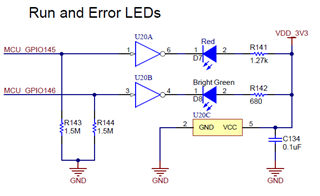
- 2 LEDs driven respectively by GPIOs, controlled by core 1 and core 2 (as debug "running" LEDs)
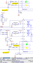
- 6 LEDs driven by the EtherCAT peripheral (as in the EVB)
I would like to understand a bit better how to electrically drive those signaling LEDs. If possible, I would like to avoid any external buffer, and connect them directly to the MCU with a resistor.
I have some doubts, based on the actual schematics of the TI Evaluation Board (TMDSCNCD28388D):
- why 4 LEDs are directly driven by the MCU GPIO (with the aforementioned connection) and the other 2 (run/error LEDs) are driven by an inverter (I suppose, acting as a buffer)?
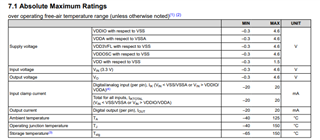
The MCU datasheets (pp. 94-95) reports that the max recommended GPIO current is |Ioh| = |Iol| = 4mA; the output resistance is Roh=Rol=35ohm for GPIOs of "group 2", that is 139 - 168 (so all, the GPIOs used by EtherCAT LEDs).
I have just made some computations and, assuming LEDs with Vf=2V, Vdd=3.3V and Iled=Ioh=4mA, the resulting external resistance to be applied is (3.3-2)V/4mA - 35ohm = 290ohm
Also, even if assuming Iout = 4mA, the resulting power dissipation for 6 LEDs is 6*35ohm*(4mA)^2 = 3.36mW (their effect should be thermally negligible, considering RthJ-A = 20.6°C/W)
Why does TI use Inverters to drive LEDs? Are they actually needed? (TI is using resistances that are a way bigger than the computed 290ohm, so the current will be lower than 4mA)
Is there any constraint on the MCU about the total GPIO current (so, supplied by VDDIO)?
Thank you!
Best regards,
Alessio