This thread has been locked.

If you have a related question, please click the "Ask a related question" button in the top right corner. The newly created question will be automatically linked to this question.

TIDM-1000: Vienna rectifier calibration and testing with 220Vrms, 50Hz ac three phase supply

Part Number: TIDM-1000
Other Parts Discussed in Thread: TMDSCNCD28379D,

Tool/software:
Hi,

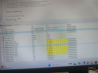
I am working with TIDM-1000 board using the control board TMDSCNCD28379D, when I am starting with BUILD1 configuration, getting the output as shown below. I didn't do any calibration for Vbus, Vac, Iac etc.Mainly the current went Irms1,2,3 went wrong. When I measured the currents using the clamp meter, the current observed are Irms1=2.5A (gui_Irms1=4.3), Irms2= 0.9A(gui_Irms2=1.4A) and Irms3=1.6(gui_Irms3=3.08Aetc. These are different from the window I have attached. My queries are

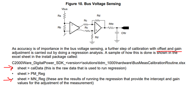
1. How to do calibration for Vbus,Vac,Iac etc? can you please explain some link or procedure?

2. Actually, I am testing with 220Vrms,50Hz ac three phase supply, so what are the changes I have to do with the settings which was not explained in design guide?

3. I have used 200ohm load at the output for the above BUILD1 openloop setup, you have suggested 500ohm load, Is it ok?

 Can you please assist me in the above problems?

with regards

Athira T P

  • Hi Athira, 

    1. its mentioned in the design guide, pls follow this. (or) you can use TINA software for checking the max AC capability with op amp gain and resistors connected. 

    2. Parameters needs to be adjusted to the 50Hz system ( your AC_FREQ_HZ = 50Hz, #define VIENNA_VAC_TYPICAL_VOLTS ((float32_t)208) to 400, and VDC = 700 instead of 600. 

    3. First, I would recommend to follow all labs as per design guide. after having a clear understanding of firmware & hardware can change according to your system needs. 

    Thanks & Regards,

    Uttam Reddy 

  • Thank you for the reply.

    1. I have already gone through the design document for the calibration procedure. Is there any step wise procedure to calibrate Vac, Irms, Vbus etc in detail. Actually, the excel files are not giving me proper idea. And after the procedure, where we have to replace the constants in the firmware code?

  • Unfortunately no other documents available.