This thread has been locked.

If you have a related question, please click the "Ask a related question" button in the top right corner. The newly created question will be automatically linked to this question.

TMS320F28335: Serial Communication.. SCITXDA & SCIRXDA

Part Number: TMS320F28335

Tool/software:

Hi TI members,

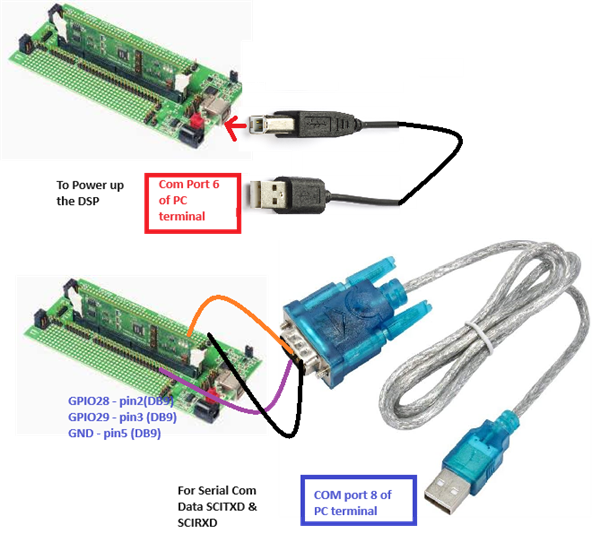
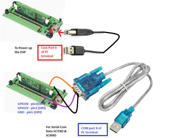
I run an example of Chap 9 F28335 Serial Communication Interface. I am using a serial RS232 cable to USB-A. Pins are connected like this: (One end of the cable is connected to the peripheral board using GPIO28, GPIO29 & Other end is connected to PC through USB-A. The pin Configuration is given below:

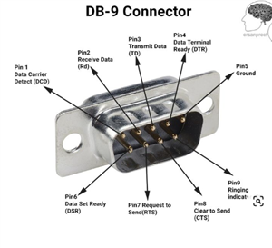
// GPIO28 is SCI_A-RXD (Connect to Pin3, PC-TX, of serial DB9 cable)..purple wire
// GPIO29 is SCI_A-TXD (Connect to Pin2, PC-RX, of serial DB9 cable)..orange wire

// Gnd of peripheral is Ground (Connect to Pin5 of serial DB9 cable)..black wire

The results are verified through Online PC terminal. Please see the pictures: 

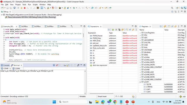
Problem is when i set everything Baudrate, Odd parity bits, data size, stop bits and COM Port 8 at terminal, I received unwanted data which I didn't send through DSP program ('The F28335 - UART is fine !') to COM port 8 of PC. Please see in picture:

COM port 8--->


Unwanted / Undersired Data----->

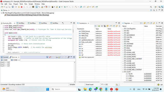
Then I connect the terminal at COM port 6 (XDS100 class 6 USB serial Port) with same setting at terminal(baud, parity...etc), where the DSP is connected through power cable via using serial connection (USB-B...USB-A), I start having a correct results. Please see pictures:


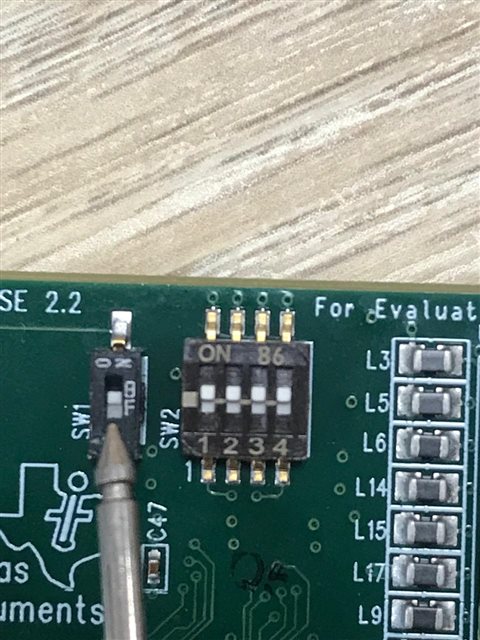
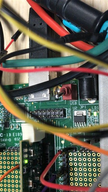
The SW1 is in Off condition, i guess (I didn't change anything)--->


I am unable to understand why I am not getting the correct results at COM port 8? 

Why I am getting unwanted/undesired results at COM port 8? I am using the right SCITXD and SCIRXD connection by using Serial cable DB9 to USB-A of the PC.

Please read carefully and suggest accordingly.

Thanks

Regards

Arsalan


  • Hi Arsalan,

    There is no issue here. COM6 is the com port you should be using to communicate with your device.

    It is known that if you do not know what COM Serial Port the device is connected to you will need to determine this. On Windows 10, this can most easily be done by searching for Device Manager in your Windows Search Bar and then scrolling down to Ports. Look for “User UART (COMX)” or “USB Serial Port (COMX)” where X represents the comport number. Your device's identified port would be COM Port 6. 

    Best Regards,

    Allison

  • Hi Allison,

    Thanks for your reply.

    Yes, I am aware of that port number to check through the device manager. Please see the picture of the device manager in the above post. That's why I shared the picture with you. COMport 6 is the port that i used it to power the DSP (USB-b to USB-A). But here is the Program code. it says that SCIATXD & SCIRXD pins (GPIO28 & GPIO29) are used for transmission and receiving data through DB9 cable (RS232 to USB-A) which I was using at COM port 8. But I see the data are receiving at the terminal (bogus/ undesired data)  but it is not like this "The F28335 - UART is fine !').. the actual data. Why ????. Then What is the purpose for SCIATXD & SCIRXD pins (GPIO28 & GPIO29)  ????. It means there is no meaning in using these GPIOs connection with DB9 which I bought for serial transmission (RS232 to USB-A) at COM port 8 of PC.

    Please correct me if I am in the wrong direction.

    Thanks 

    Regards

    Arsalan

  • Hi Arsalan,

    So to clarify, you have a USB to UART bridge at one COM port but you are trying to connect a DB9 cable at another COM port, but it sounds like you are trying to use the same pins for both (where GPIO28 and 29- are pinned out)?

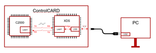
    The switch (SW1) on the control card should be in "off" position to enable the serial emulation using the FTDI chip. With this, the SCI comms will be handled over the same USB connection that is providing the JTAG link. There is no need for extra connection to achieve the SCI connections on this board. 

    Are you simply trying to scope those SCI pins for DB9? Also wanted to check if you have any jumpers placed on your setup?

    Best Regards,

    Allison

  • Hi Allison,

    Thanks for your reply.

    it sounds like you are trying to use the same pins for both (where GPIO28 and 29- are pinned out)?

    As I said above, I am trying to send & receive data through COM port 8 instead of COM port 6. The program code(shared above) clearly defines how you can send & receive data through GPIO28 & GPIO29 and I connected these pins with DB9 to the USB-A cable at COM port 8 of the PC terminal. (Picture shared above in post)

    COM port 6 through which I am powering up(supply power) the DSP shouldn't work as serial comm which I want. That's why COM port 8 is used. The problem here is that I am receiving incorrect data. I should have the correct data ('The F28335 - UART is fine !') to COM port 8 of the PC. 

    Are you simply trying to scope those SCI pins for DB9? Also wanted to check if you have any jumpers placed on your setup?

    Yes. I don't know much about the jumper in this board, especially for serial comm. The SW1 is discussed in the manual for serial comm, which must be off. I shared the picture with you in the post above.

    Please suggest accordingly to resolve this issue.

    Regards

    Arsalan 

  • Hi Arsalan,

    Thank you for the information. Please allow for another day for me to gather some information and form a response. Thank you kindly for your patience.

    Best Regards,

    Allison

  • Hi Allison,

    Thanks for your reply. I will wait for your response or suggestion.

    Best Regards

    Arsalan

  • Hi Arsalan,

    You can either flip the switch to use the XDS to USB connection built into the controlCARD, or you can flip the switch the opposite way to use the header pins of the docking station for those SCI GPIOs (GPIO28/29). When you flip the switch the opposite way, are you able to correctly use your DB9?

    To double check, are you also configuring GPIO28/29 as SCI correctly as input or output (for RX or TX)?

    Can you please clarify why you are trying to use both USB connection and DB9 at the same time on the same SCI module since they perform the same function (on different COM ports)?

    Best Regards,

    Allison

  • Hi TI members,

    Code: (I am sending data Code =123)


    You can either flip the switch to use the XDS to USB connection built into the controlCARD, or you can flip the switch the opposite way to use the header pins of the docking station for those SCI GPIOs (GPIO28/29). When you flip the switch the opposite way, are you able to correctly use your DB9?

    To double check, are you also configuring GPIO28/29 as SCI correctly as input or output (for RX or TX)?

    Answers to the Above two Questions:

    1-  As you can see in the picture: I have checked and confirmed the position of the SW1 (upward--ON). I have also checked on other positions of SW1 as         well if I am making any mistakes. Both positions are checked too. But the right position is upward for ON condition. 

         Switch SW1 (upward-ON)


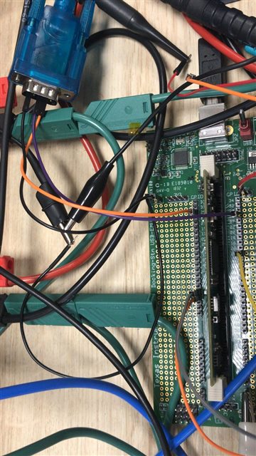
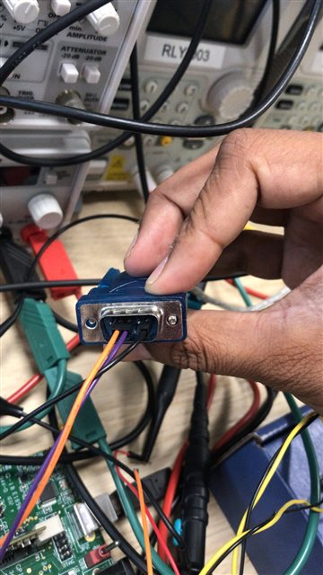
    2- For DB9 connection, (Orange = GPIO29, Purple = GPIO28).

    3- The DB9 Connection... [Pin2 from Left = GPIO29(Orange), Pin3 = GPIO28(Purple)],

         Pin5 is Ground Connection(always)

         Note: Also I have checked by swapping the GPIO pin 28 / 29 or Pin2 / Pin3 for DB9

    Can you please clarify why you are trying to use both USB connection and DB9 at the same time on the same SCI module since they perform the same function (on different COM ports)?

    Answer to the Question:

    As I said, The USB connection is used for Power up the DSP board ( Connected at COM port 6) and DB9 is for serial communication at COM port 8.

    The Results at COM port 6 and COM port 8 are given as follows at CCS terminal See both pictures at below:

    COM port 8 is not receiving the correct data: (Count = 123) which is a problem. It should receive the same data as COM port 6. I have tried all solutions by changing SW1 positions and the DB9 connection for TX and RX. The Problem is still there:

    Please suggest accordingly. The TI members can also help.

    Best Regards

    Arsalan

  • Hi Arsalan,

    If SW1 is in the ON position (as you have shown), the SCIA TX and RX signals on the F28335 will be routed to the UART-to-USB converter on the ControlCARD and will not be brought out to the header pins you are connecting the DB9 cables to. If you want to use the DB9 cable to convert the signal instead of the UART-to-USB converter built into the ControlCARD, you will need to move SW1 to the OFF position. Using SCIA you cannot simultaneously use these 2 COM ports at once since the SW1 position will route the SCI pins to either the header pins or the built-in UART-to-USB converter (not both).

    With the SW in the OFF position, please scope the SCIATX header pin to verify that you are seeing a UART signal.

    • If you see the correct UART signals, the issue is related to your DB9 cable.
    • If you are not seeing the correct UART signals, the issue is likely related to incorrect GPIO configurations.

    Best Regards,

    Delaney

  • Dear Delaney Woodward,

    Thanks for the clarification.  I can see pulses when I connect the Oscilloscope with GPIO29 (SCI_TXD) for transmitting data. Db9 could be a problem. Therefore I will not use DB9 to transmit & receive data. I will move on to UART- USB Connection.

    Thanks

    Best Regards

    Arsalan