This thread has been locked.

If you have a related question, please click the "Ask a related question" button in the top right corner. The newly created question will be automatically linked to this question.

TMS320F280049: How to measure the device junction temperature?

Part Number: TMS320F280049

Tool/software:

Hi Team,

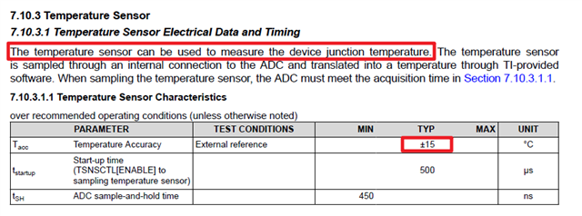
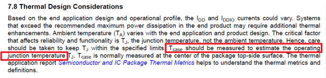
In the datasheet of F280049, the are two methods to measure device junction temperature, one is use internal Tempsensor, but have a poor temperature accuracy. Another way is use Thermal Resistance Characteristics to calculate  device junction temperature.

1. So Which way is more accuracy? 

2.How to calibrate internal temperature sensor, to get accuracy temperature?

3.Whether it is feasible to place thermal pads on the DSP and whether there is a stress risk?

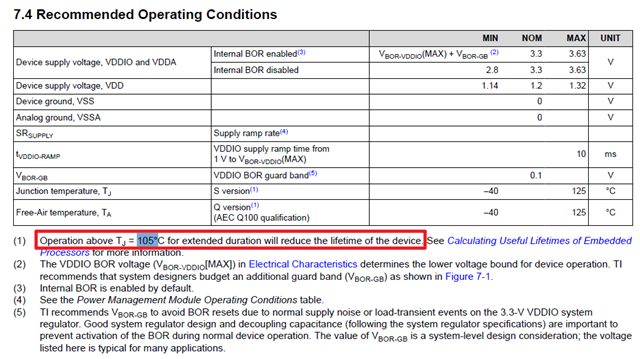
4.It mentioned that over 105℃ will decrease the life of device, how measure this temperature?
 

Best Regards,

Zane

  • Zane,

    1. So Which way is more accuracy? 

    The calculated method by measuring Tcase and using the formula based on ROjc co-efficient and device power consumption will be the most accurate method.  Some background the DS limits you mention; the temperature sensor output voltage is non-linear, which makes the calibration function more challenging to implement.  The most deviations occur at temperatures below 0C.  If customer is operating in the 25C to 125C region the error should be less that the full +/-15C, maybe on the order of half.  Customer should check this out on a few devices for themselves.

    4.It mentioned that over 105℃ will decrease the life of device, how measure this temperature?
    I'm going to answer this question before the others, as it may help shape what the customer needs to do in their system, or if this is not a concern.  Please reference this app note on calculating derating factor of >105C on the device. https://www.ti.com/lit/an/sprabx4b/sprabx4b.pdf If the temperature profile of the customer system is not always 105C and above, then periodic times >105C may not have meaningful impact to the life of the device(i.e. if a good portion of the life of the device is spent at a temperature below 105C then this will increase the lifetime of the device over the 105C usecase)

    2.How to calibrate internal temperature sensor, to get accuracy temperature?

    3.Whether it is feasible to place thermal pads on the DSP and whether there is a stress risk?

    Thermal pad is fine to measure Tcase, if customer is only concerned with 105C boundary and it is possible to force 105C in their factory, they could simply look for this ADC conversion value from the temp sensor and set up an ISR, etc.   

    If this is not feasible, customer will need to look at converting at least 2 different temp sense values to create a best fit line to correct the temperature sensor output.  The closer they can get these temperatures to 105C(assuming this is the main concern), the better. 

    The temperature sensor behavior is not ideally linear, but more polynomial in nature.  This is accounted for in our default calibration, but over the full temp of the device we can only give the +/-15C you see in the DS.  If customer is only looking at room temp or above, this error should be somewhat less(colder temps have more error) as I mentioned above.

    Best,

    Matthew