This thread has been locked.

If you have a related question, please click the "Ask a related question" button in the top right corner. The newly created question will be automatically linked to this question.

TMS320F28379D: Routing XCLKOUT from GPIO73 to GPIO Output XBAR1 on Launchpad28379D

Part Number: TMS320F28379D
Other Parts Discussed in Thread: SYSCONFIG

Tool/software:

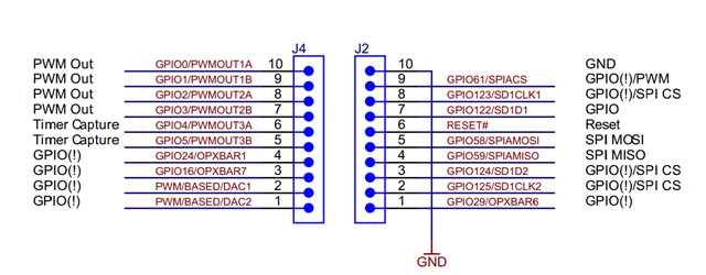
I am evaluating the TMS320F28379D processor via the Launchpad28379D and creating my own project from the examples provided using the Bit field header files. I can get the GPIO and interrupts set up and working and wanted to check the clocks of the system. Reading through the technical manual I found that the XCLKOUT can be used to output the clock on GPIO73. However this pin is only routed to the high density connector on the back of the launchpad. I found a related forum post where the solution is to use the XBAR to route the clock signal from the GPIO73 to the GPIO Output XBAR. The goal is to route the clock signal on GPIO73 to InputXBAR1 and then to GPIO output XBAR1 (GPIO24) on a scope. I am having trouble and so far all I can see is a 200mV 60Hz signal on the pin no matter what clock source is congfigured. From the information in the technical manual I have set the following regesters with the following commands: 

  //Want to make GPIO73 output XCLK but needs 69 clock cycles between writes so write this at the beginning
ClkCfgRegs.CLKSRCCTL3.bit.XCLKOUTSEL = 6; //Select the INTOSC2 for now

 /*Output the system clock on GPIO73 to monitor on scope*/

GpioCtrlRegs.GPCMUX1.bit.GPIO73 = 3; // Set mux to XCLK
GpioCtrlRegs.GPCDIR.bit.GPIO73 = 1;    //Set as output
GpioCtrlRegs.GPAPUD.bit.GPIO24 = 0; // Enable pullup on GPIO24
GpioCtrlRegs.GPADIR.bit.GPIO24 = 1; //Set to output
GpioCtrlRegs.GPAMUX2.bit.GPIO24 = 1; //Set mux so pin 24 is XBAROUT0
//Need to route this pin to the INPUT XBAR, to then route to OUTPUTXBAR since
//This pin 73 is not brought out from package on the Launchpad!!
OutputXbarRegs.OUTPUTLOCK.bit.LOCK = 0;
InputXbarRegs.INPUTSELECTLOCK.bit.INPUT1SELECT = 0;
InputXbarRegs.INPUT1SELECT = 73;
OutputXbarRegs.OUTPUT1MUX0TO15CFG.bit.MUX1 = 0x1;
OutputXbarRegs.OUTPUT1MUXENABLE.bit.MUX1 = 1;
OutputXbarRegs.OUTPUTLATCHENABLE.bit.OUTPUT1 = 0;
OutputXbarRegs.OUTPUTINV.bit.OUTPUT1 = 0;

Please advise if I have neglected to set a particular register or why I may not be able to see the clock outputting on GPIO24. 

Thank you for your time

  • Hi Mike,

    I've tested this successfully on GPIO25 on a F28379D launchpad, it doesn't seem like GPIO24 is available on the launchpad. Can you send a snapshot of how you've connected GPIO24?

    Thank you,

    Luke

  • Hi Luke,

    From the launchpad overview document it shows that GPIO24 is connected to pin 4 of expansion header J4

    Also in the technical manual for the GPIO mux settings GPIO24 can be set to OUTPUTXBAR1 by setting mux to 1

    So for my code I have the following setup for the GPIO pin 24:

    GpioCtrlRegs.GPAPUD.bit.GPIO24 = 0; // Enable pullup on GPIO24
    GpioCtrlRegs.GPADIR.bit.GPIO24 = 1; //Set to output
    GpioCtrlRegs.GPAMUX2.bit.GPIO24 = 1; //Set mux so pin 24 is XBAROUT1

    And am just connecting to the external header J4 pin 4 with my scope probe and grounding via J2 pin 10.

    I will try and get the OUTPUTXBAR2 on GPIO25 working like you mentioned you were able to do.

    Best regards,

    -Mike

  • Hi Mike,

    My mistake, I also see the GPIO24 on the launchpad now, not sure how I missed that initially.

    I tested this on GPIO25 as well and it worked, however I used SysConfig for my configuration. The only difference I noticed between my configuration and yours is that I did not enable the internal pull up on GPIO24. Could you try disabling this?

    Thank you,

    Luke

  • Hey Luke,

    I tried commenting out the line setting internal pullup on GPIO24 and still no luck. I wonder if i need to change anything else in the clock configuration registers. So far I am only using the following for that register: 

    ClkCfgRegs.CLKSRCCTL3.bit.XCLKOUTSEL = 2; //Select the cpu1.sysclock for now

    From there I set the mux for the GPIO pins (both I set as outputs, setting GPIO73 as input makes no difference atm). 

    GpioCtrlRegs.GPCDIR.bit.GPIO73 = 1; //Set to input or leave as output?
    GpioCtrlRegs.GPCMUX1.bit.GPIO73 = 3; // Set mux to XCLK

    //GpioCtrlRegs.GPAPUD.bit.GPIO24 = 0; // Enable pullup on GPIO24
    GpioCtrlRegs.GPADIR.bit.GPIO24 = 1; //Set to output
    GpioCtrlRegs.GPAMUX2.bit.GPIO24 = 1; //Set mux so pin 24 is XBAROUT1

    Finally I set up the input and output XBARs as follows: 

    InputXbarRegs.INPUT1SELECT = 73;
    OutputXbarRegs.OUTPUT1MUX0TO15CFG.bit.MUX1 = 0x1;
    OutputXbarRegs.OUTPUT1MUXENABLE.bit.MUX1 = 1;
    OutputXbarRegs.OUTPUTLATCHENABLE.bit.OUTPUT1 = 0;
    OutputXbarRegs.OUTPUTINV.bit.OUTPUT1 = 0;

    From here I am going to try switching to GIO25 and OUTPUTXBAR2 as you had done and see if that works. If not, then i'm sure I am just overlooking something in the setup of the clock register, gpio register, and input output XBAR register. 

    Thank you for your time and help with this,

    Best,

    -Mike

  • Hi Mike,

    I would recommend starting from scratch with an empty project and using SysConfig to accomplish this, that should result in the exact same configuration that I'm using on my side.

    Here's my .syscfg file:

    /**
     * These arguments were used when this file was generated. They will be automatically applied on subsequent loads
     * via the GUI or CLI. Run CLI with '--help' for additional information on how to override these arguments.
     * @cliArgs --device "F2837xD" --part "F2837xD_337ZWT" --package "F2837xD_337ZWT" --context "CPU1" --product "C2000WARE@5.03.00.00"
     * @v2CliArgs --device "TMS320F28379D" --package "337ZWT" --context "CPU1" --product "C2000WARE@5.03.00.00"
     * @versions {"tool":"1.21.0+3687"}
     */
    
    /**
     * Import the modules used in this configuration.
     */
    const inputxbar_input  = scripting.addModule("/driverlib/inputxbar_input.js", {}, false);
    const inputxbar_input1 = inputxbar_input.addInstance();
    const other            = scripting.addModule("/driverlib/other.js", {}, false);
    const other1           = other.addInstance();
    const outputxbar       = scripting.addModule("/driverlib/outputxbar.js", {}, false);
    const outputxbar1      = outputxbar.addInstance();
    
    /**
     * Write custom configuration values to the imported modules.
     */
    inputxbar_input1.$name         = "myINPUTXBARINPUT0";
    inputxbar_input1.inputxbarGpio = "GPIO73";
    
    other1.$name                    = "myOTHER0";
    other1.useCase                  = "CUSTOM";
    other1.useInterfacePins         = ["XCLKOUT"];
    other1.other.$assign            = "OTHER";
    other1.other.xclkoutPin.$assign = "GPIO73";
    
    outputxbar1.$name                            = "myOUTPUTXBAR0";
    outputxbar1.useSourceSelect                  = true;
    outputxbar1.sourceSignals                    = ["INPUTXBAR1"];
    outputxbar1.outputxbar.outputxbarPin.$assign = "GPIO24";
    
    /**
     * Pinmux solution for unlocked pins/peripherals. This ensures that minor changes to the automatic solver in a future
     * version of the tool will not impact the pinmux you originally saw.  These lines can be completely deleted in order to
     * re-solve from scratch.
     */
    outputxbar1.outputxbar.$suggestSolution = "OUTPUTXBAR1";
    

    Let me know if you have any additional questions.

    Thank you,

    Luke.