This thread has been locked.

If you have a related question, please click the "Ask a related question" button in the top right corner. The newly created question will be automatically linked to this question.

TMDSHVMTRINSPIN: Which parameters can I change while fulfilling requirements of User's parameters using hvkit?

Part Number: TMDSHVMTRINSPIN
Other Parts Discussed in Thread: CONTROLSUITE, C2000WARE, , MOTORWARE

Tool/software:

I wondered which parameters I can change (except parameters of my motor) during my own tuning process when using hvkit with F28069M ISO Control Card? When I was implementing projects of labs on my experimenal motor, I met some error code like ctrl_Freq high or est_Freq low or some other error code. 

  • What are the exact error codes that you saw? What aspects of the HW/SW are you trying to change?

    Regards,
    Jason Osborn

  • I was trying to implement lab 21 on my own motor, after satisfying with no User_errocode existing by adjusting IQ_Full_Scale frequency, voltage, current and USER_PWM_Freq. I enabled the system and I saw the value of speed, torque, VdcBus kept changing in a wide range, I wondered am I setting some of the value wrong or any restricts I did not satisfy, which results the failure. 

  • When you change a motor and your hardware, any or all of the following may require change, as different systems have different physical parameters:

    • Dependent on motor:
      • USER_IQ_FULL_SCALE_FREQ_Hz
      • USER_MOTOR
      • Check almost all parameters in the motor-dependent section immediately below the USER_MOTOR #define
    • Dependent on the rest of the HW:
      • USER_ADC_FULL_SCALE_VOLTAGE_V
      • USER_ADC_FULL_SCALE_CURRENT_A
    • Dependent on HW and motor:
      • USER_IQ_FULL_SCALE_VOLTAGE_V
      • USER_IQ_FULL_SCALE_CURRENT_A
    • MCU settings:
      • USER_SYSTEM_FREQ_MHz
        • Sys Clock frequency
      • USER_PWM_FREQ_kHz
        • PWM frequency
      • USER_MAX_ACCEL_Hzps
        • An unstable system, or one where the PI controller values have not yet been tuned, may require this value to be lowered

    This may not necessarily be a comprehensive list. However, do you see anything here that you need to adjust? Refer to inline comments in user.h for details on how/what to change.

    Regards,
    Jason Osborn

  • #define USER_IQ_FULL_SCALE_FREQ_Hz        (128.0)   // 800 Example with buffer for 8-pole 6 KRPM motor to be run to 10 KRPM with field weakening; Hz =(RPM * Poles) / 120
    
    #define USER_IQ_FULL_SCALE_VOLTAGE_V      (470)   // 24.0 Example for drv8301_revd typical usage and the Anaheim motor
    
    #define USER_ADC_FULL_SCALE_VOLTAGE_V       (470)      // 66.32 drv8301_revd voltage scaling
    
    #define USER_VOLTAGE_SF               ((float_t)((USER_ADC_FULL_SCALE_VOLTAGE_V)/(USER_IQ_FULL_SCALE_VOLTAGE_V)))
    
    #define USER_IQ_FULL_SCALE_CURRENT_A          (12.5)   // 41.25 Example for drv8301_revd typical usage
    
    #define USER_ADC_FULL_SCALE_CURRENT_A        (25)     // 82.5 drv8301_revd current scaling
    
    #define USER_CURRENT_SF               ((float_t)((USER_ADC_FULL_SCALE_CURRENT_A)/(USER_IQ_FULL_SCALE_CURRENT_A)))
    
    #define USER_NUM_CURRENT_SENSORS            (3)   // 3 Preferred setting for best performance across full speed range, allows for 100% duty cycle
    
    #define USER_NUM_VOLTAGE_SENSORS            (3) // 3 Required
    
    #define   I_A_offset    (0.003593325615)     //(0.9939797521)
    #define   I_B_offset    (0.06045937538)      //(1.014363647)
    #define   I_C_offset    (0.329120934)        //(1.005615234)
    
    #define   V_A_offset    (0.03011131287)      //(0.5020679235)
    #define   V_B_offset    (0.7957363725)       //(0.4977650046)
    #define   V_C_offset    (0.03015857935)      //(0.4986107945)
    
    
    //! \brief CLOCKS & TIMERS
    // **************************************************************************
    //! \brief Defines the system clock frequency, MHz
    #define USER_SYSTEM_FREQ_MHz             (90.0)
    
    #define USER_PWM_FREQ_kHz                (20.0) //30.0 Example, 8.0 - 30.0 KHz typical; 45-80 KHz may be required for very low inductance, high speed motors
    
    
    #define USER_MAX_VS_MAG_PU        (0.5)    // Set to 0.5 if a current reconstruction technique is not used.  Look at the module svgen_current in lab10a-x for more info.
    
    #define USER_CTRL_HANDLE_ADDRESS   (0x13C40)
    
    #define USER_EST_HANDLE_ADDRESS    (0x13840)
    
    #define USER_VD_SF                 (0.95)
    
    #define USER_PWM_PERIOD_usec       (1000.0/USER_PWM_FREQ_kHz)
    
    #define USER_ISR_FREQ_Hz           ((float_t)USER_PWM_FREQ_kHz * 1000.0 / (float_t)USER_NUM_PWM_TICKS_PER_ISR_TICK)
    
    #define USER_ISR_PERIOD_usec       (USER_PWM_PERIOD_usec * (float_t)USER_NUM_PWM_TICKS_PER_ISR_TICK)
    
    
    //! \brief DECIMATION
    // **************************************************************************
    //! \brief Defines the number of pwm clock ticks per isr clock tick
    //!        Note: Valid values are 1, 2 or 3 only
    #define USER_NUM_PWM_TICKS_PER_ISR_TICK        (3)
    
    #define USER_NUM_ISR_TICKS_PER_CTRL_TICK       (2)      // 2 Example, controller clock rate (CTRL) runs at PWM / 2; ex 30 KHz PWM, 15 KHz control
    
    #define USER_NUM_CTRL_TICKS_PER_CURRENT_TICK   (1)      // 1 Typical, Forward FOC current controller (Iq/Id/IPARK/SVPWM) runs at same rate as CTRL. 
    
    #define USER_NUM_CTRL_TICKS_PER_EST_TICK       (1)      // 1 Typical, FAST estimator runs at same rate as CTRL;
    
    #define USER_MAX_ACCEL_Hzps                 (5.0)      // 20.0 Default
    
    #define USER_NUM_CTRL_TICKS_PER_SPEED_TICK  (15)   // 15 Typical to match PWM, ex: 15KHz PWM, controller, and current loop, 1KHz speed loop
    
    #define USER_NUM_CTRL_TICKS_PER_TRAJ_TICK   (15)   // 15 Typical to match PWM, ex: 10KHz controller & current loop, 1KHz speed loop, 1 KHz Trajectory
    
    #elif (USER_MOTOR == My_Motor)
    #define USER_MOTOR_TYPE                 MOTOR_Type_Pm
    #define USER_MOTOR_NUM_POLE_PAIRS       (4)
    #define USER_MOTOR_Rr                   (NULL)
    #define USER_MOTOR_Rs                   (4.4752541)
    #define USER_MOTOR_Ls_d                 (0.06000000)
    #define USER_MOTOR_Ls_q                 (0.08000000)
    #define USER_MOTOR_RATED_FLUX           (3.07803010)
    #define USER_MOTOR_MAGNETIZING_CURRENT  (NULL)
    #define USER_MOTOR_RES_EST_CURRENT      (1.0)
    #define USER_MOTOR_IND_EST_CURRENT      (-1.0)
    #define USER_MOTOR_MAX_CURRENT          (5.0)
    #define USER_MOTOR_FLUX_EST_FREQ_Hz     (20.0)
    #define IPD_HFI_EXC_FREQ_HZ             (500.0)       // excitation frequency, Hz
    #define IPD_HFI_LP_SPD_FILT_HZ          (10.0)        // lowpass filter cutoff frequency, Hz
    #define IPD_HFI_HP_IQ_FILT_HZ           (20.0)        // highpass filter cutoff frequency, Hz
    #define IPD_HFI_KSPD                    (50)        // the speed gain value
    #define IPD_HFI_EXC_MAG_COARSE_PU       (0.4)         // coarse IPD excitation magnitude, pu
    #define IPD_HFI_EXC_MAG_FINE_PU         (0.2)         // fine IPD excitation magnitude, pu
    #define IPD_HFI_EXC_TIME_COARSE_S       (0.6)         // coarse wait time, sec max 0.64
    #define IPD_HFI_EXC_TIME_FINE_S         (0.6)         // fine wait time, sec max 0.4
    #define AFSEL_FREQ_HIGH_PU              (_IQ(20.0 / USER_IQ_FULL_SCALE_FREQ_Hz))
    #define AFSEL_FREQ_LOW_PU               (_IQ(10.0 / USER_IQ_FULL_SCALE_FREQ_Hz))
    #define AFSEL_IQ_SLOPE_EST              (_IQ((float)(1.0/0.1/USER_ISR_FREQ_Hz)))
    #define AFSEL_IQ_SLOPE_HFI              (_IQ((float)(1.0/1.0/USER_ISR_FREQ_Hz)))
    #define AFSEL_IQ_SLOPE_THROTTLE_DWN     (_IQ((float)(1.0/0.05/USER_ISR_FREQ_Hz)))
    #define AFSEL_MAX_IQ_REF_EST            (_IQ(0.4))
    #define AFSEL_MAX_IQ_REF_HFI            (_IQ(0.4))
    This is how I set the value of User.h. After receiving your reply I realized that maybe I didn't set the value that corresponds to my motor and hardware, so I tried to check for that. The value I got for USER_ADC_FULL_SCALE_VOLTAGE_V and USER_ADC_FULL_SCALE_CURRENT_A are from GUI composer, also the Rs and rated flux value of my motor. I found another problem while trying to get the corresponding current/voltage offset value to my hardware, and the values are shown in the preceding bracket, obviously while getting these values the rotor is not running, so I may had wrong values. However, during reading of the labs' document, I think getting offset values through lab03a didn't need any additional change to the parameters, so it refers to that I am setting some of the values wrong, Could you please check for my parameter settings and point out where did I made the mistake and how to get it done correctly. Also for lab21.

    Thanks.

  • Incorrect offset values are a big sign that something in the hardware setup is wrong. Unless setup/configuration code was changed, it's not usually a parameter issue.

    • What are the states of the controlCard switches? Verify these states against the TMDSHVMTRINSPIN HW user's guide document, located in either controlSuite or C2000Ware Motor Control SDK. Location:


    • Is power hooked up correctly?

    Regards,
    Jason Osborn

  • I did't notice these files until you answered and I took a glance at the material that you pointed out, it seems that I overloaded and no other problems found. I was implementing the kit on a 1.5kw IPMSM motor, should I change the motor to less than 750w? Another question is that the system was energized by 220V AC power, should I input 15V DC  external power simultaneously with the 220V AC power? Looking forward for your reply and if the answer is yes, I am gonna change the motor and test on it a few days after.

  • Hello,

    • You should definitely stay below the rated power of the kit. As the HW guide says, the power and PFC stages of the kit are rated for 750W, so a lower power motor should be used to test.
    • For 15VDC, refer to this text from the HW guide. The 15VDC bus can be generated by the PFC output.

    Hope that was helpful!

    Regards,
    Jason Osborn

  • Hello,

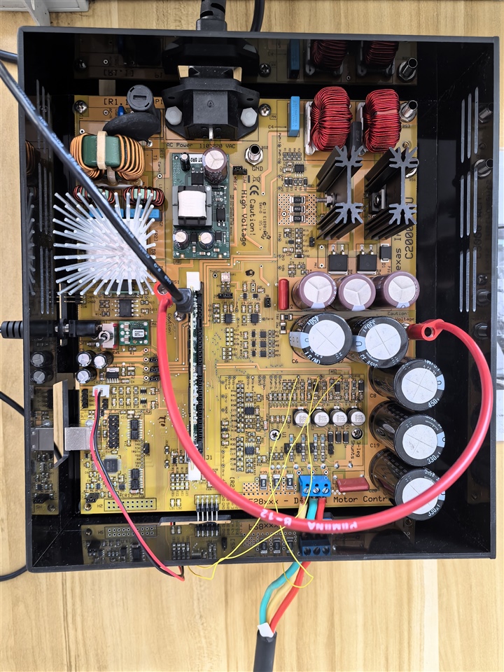
    Ipost up the picture of the hardware, I thought I set the hardware up correctly.

    I changed the motor and tried, the result was the same. I also wondered that I succeeded running the motor with the GUI Composer, but with CCS the motor cannot run successfully. Does that mean the hardware setup was correct but something was wrong with the parameters or the program itself?

    Thanks.

  • If the motor succeeds with the kit's GUI but not in CCS, the most likely problem is that the CCS project is not correctly set up. What is the .projectspec file you're using?

    Regards,
    Jason Osborn

  • D:\TI\motorware_1_01_00_18\sw\solutions\instaspin_foc\boards\drv8301kit_revD\f28x\f2806xF\projects\ccs\proj_lab21

    I used the project following this directory. I wanted to implement lab21 on my motor, but I couldn't find lab21 under hvkit, so I used the proj_lab21 under this directory. Maybe I used the wrong one. If so, could you please tell me the correct directory, where lies the project that I should use.

    Thanks.

  • The HVKIT does not appear to have Lab 21 implemented in MotorWare. To implement Lab 21, you would need to read through the lab documentation and determine what further changes would need to be made from the existing projects to implement lab 21 yourself. Using Lab 21 from a different HW kit is not going to work. The different HW has different requirements and implementation differences.

    Regards,
    Jason Osborn

  • Is there any existing project I can implement with HVKIT to realize high-frequncy signal injection method?

  • Refer to the lab documentation and available projects. If it is not listed there, you may need to implement custom firmware.

    Regards,
    Jason Osborn

  • Thanks Jason for your reply.

    I got some other questions that I want to consult. From the table listed in lab document the hvkit seems to have the capability to run high frequncy injection, but why there is no existing project for it like drv8301kit? Since I have TMS320F28069MPZT F2806x ISO controlCard with hvkit, does that mean I can implement any FOC and MOTION lab project, which listed under the directory of hvkit_rev1p1 such as lab11a? Looking forward for your reply.

    Thanks.

  • I'm unsure why the InstaSPIN Labs document lists the HVKIT as having that functionality. As far as I am aware, that is incorrect.

    The ...xF controlCard is capable of implementing any InstaSPIN-FOC project in the appropriate kit and device directory, while the ...xM controlCard is capable of implementing any InstaSPIN-FOC or InstaSPIN-MOTION project in the appropriate kit and device directory.

    Regards,
    Jason Osborn