Part Number: TMS320F28388D
Other Parts Discussed in Thread: C2000WARE
Tool/software:
I want to understand how to configure the CM clock, because the current clock is only 25 MHz instead of 125 MHz.
CPU1 is programmed with bit-field libraries, CM is programmed with the driverlib.
I used CPU Timer 0 to verify the clock frequency of the CM core. The code is based on the timer example "timer_ex1_cputimers". The period is set to 500 us (499 * 125 cycles).
CPUTimer_setPeriod(CPUTIMER0_BASE, 125*499);
The ISR toggels a GPIO. The PWM frequeny should be 1 kHz, but is only 200 Hz. From this I conclude that the CM clock is 25 MHz.
In the next step I verified PLLSYSCLK with the ePWM1 module of CPU1 with the result, the CPU1 clock is 200 MHz
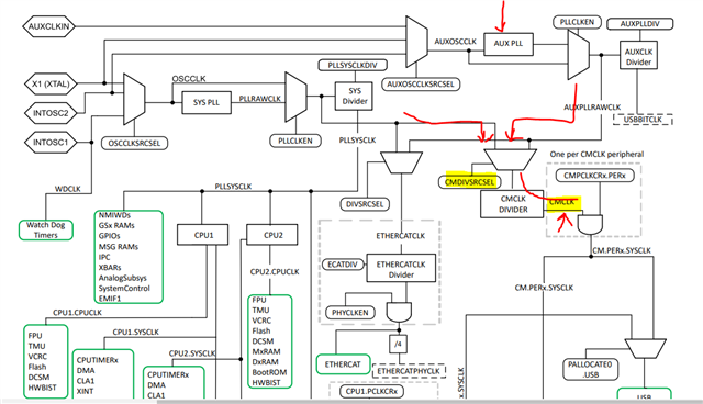
In the TMS320F2838x Technical Reference Manual (SPRUII0C), chapter 3.7, figure 3-6 shows the clocking system. CMCLK can be sourced from PLLSYSCLK or AUXPLLRAWCLK (PLLSYSCLK is selected) and can only be devided by "CMCLK DEVIDER" (register ClkCfgRegs.CMCLKCTL.CMCLKDIV). With this register, the PLLSYSCLK can be devided by /1 /2 /3 /4 /5 /6 /7 /8. How can the CM be configured to run witz 125 MHz when PLLSYSCLK is 200 MHz? With the possible deviders a CM clock rate of 200 MHz, 100 MHz, 66.7 MHz, 50 MHz, 40 MHz, 33.3 MHz, 28,6 MHz and 25 MHz are possible.
My code and the used values are derived from the examples:
ClkCfgRegs.CMCLKCTL.all = ~0xF0U | ( ((0x1 & 0x07U) << 0x05U) | ((0x1 & 0x01U) << 0x04U) );
So CMCLKDIV is 7 (for /8). That means CMCLK = 200 MHz /8 = 25 MHz. With CMCLKDIV = 0 the CMCLK is 200 MHz. I thought the clock rate can't be higher than 125 MHz.
Where is my comprehension problem?