This thread has been locked.

If you have a related question, please click the "Ask a related question" button in the top right corner. The newly created question will be automatically linked to this question.

TMS320F28P650DK: Is it possible to send 40 bits via spi?

Part Number: TMS320F28P650DK

Tool/software:

Hi everyone,

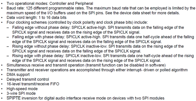
I have a slave (MC33772B) with which I want to communicate via SPI. This expects a message of 40 bits, but unfortunately my board can only send 16 bits.

Is it still possible to send 40 bits with the board or is it not designed for that? Or am I misunderstanding something?

(There is an MC33664 between the communication for isolation)


I would be very grateful for any tip.

Best regards

  • Hi :)

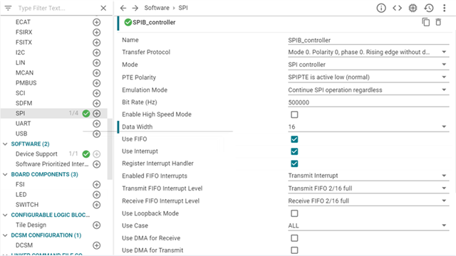
    If I set the data width to 16 in the sysconf I can insert this command as desired and can therefore send the multiple of 16 bits (here 64Bits) in a chip select:


    The problem is that 40 is not a multiple of 16. That's why I just set the data width to 8 in the sysconf. However, I can no longer execute SPI_writeDataNonBlocking(SPIB_BASE, 0xAA). No data is visible on the oscilloscope (chip select and clk are visible but not data). What else do I have to change so that I can execute the command more often in order to be able to send a multiple of 8 bits?


    My code:

    #include "driverlib.h"
    #include "device.h"
    #include "board.h"
    
    //
    // Globals
    //
    volatile uint16_t receiveData;
    volatile uint16_t slaveReady = 0;
    volatile uint16_t masterReady = 0;
    volatile uint16_t counter = 1;
    
    //
    // Function Prototypes
    //
    __interrupt void spibTxFIFOISR(void);
    __interrupt void spiaRxFIFOISR(void);
    
    //
    // Main
    //
    void main(void)
    {
        uint16_t i;
    
        //
        // Initialize device clock and peripherals
        //
        Device_init();
    
        //
        // Disable pin locks and enable internal pullups.
        //
        Device_initGPIO();
    
        //
        // Initialize PIE and clear PIE registers. Disables CPU interrupts.
        //
        Interrupt_initModule();
    
        //
        // Initialize the PIE vector table with pointers to the shell Interrupt
        // Service Routines (ISR).
        //
        Interrupt_initVectorTable();
    
        //
        // Board initialization
        //
        Board_init();
        //
        // Enable Global Interrupt (INTM) and realtime interrupt (DBGM)
        //
        EINT;
        ERTM;
    
        //
        // Loop forever. Suspend or place breakpoints to observe the buffers.
        //
        while (1)
        {
            ;
        }
    }
    
    //
    // SPI B Transmit FIFO ISR
    //
    __interrupt void spibTxFIFOISR(void)
    {
        uint16_t i = 0;
    
        //
        // Send data
        //
    
        while (i < 10000)
        {
            i++;
        }
    
        SPI_writeDataNonBlocking(SPIB_BASE, 0xAA);
        SPI_writeDataNonBlocking(SPIB_BASE, 0xAA);
    
        SPI_writeDataNonBlocking(SPIB_BASE, 0xAA);
        SPI_writeDataNonBlocking(SPIB_BASE, 0xAA);
    
        //
        // Clear interrupt flag and issue ACK
        //
        SPI_clearInterruptStatus(SPIB_BASE, SPI_INT_TXFF);
        Interrupt_clearACKGroup(INT_SPIB_controller_TX_INTERRUPT_ACK_GROUP);
    
    }
    
    //
    // Enabled only for SysConfig functionality
    //
    __interrupt void INT_SPIB_controller_RX_ISR(void)
    {
        //
        // Issue ACK
        //
        Interrupt_clearACKGroup(INT_SPIB_controller_RX_INTERRUPT_ACK_GROUP);
    
    }
    
    //
    // End of file
    //


    I would be very grateful for any help :)

  • Ah ok I know why:


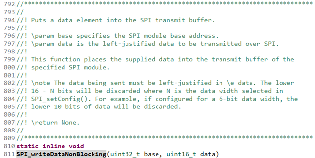
    So if I write SPI_writeDataNonBlocking(SPIB_BASE, 0xAA), then it actually says 0x00AA. That means the AA are discarded. So I have to write 0xAA00.

    Thank you very much anyway :)