Tool/software:
Hello,
I am generating a PWM for Phase shift PWM converter. I have a question regarding turning ON/OFF of PWM (turning OFF anf Turning ON) at very light loads or no-load condition.
So, the ADC sampling and acquisition happens at TBCTR=TBPRD and an ISR is called as soon as the last ADC channel acquisition is finished. The CMPA value however is updated at TBCTR=0.
In order to replicate the burst mode, I have created a variable Vdc_pu1. If Vdc_pu1>410, I would like to turn off the pwm and if Vdc_pu1<390, I would like to turn on the PWM. But I want to do this as a known point of TBCTR =0. In order to do that, I started with the AQCSRFC register. Inside ISR I have the below code
if(Vdc_pu1 > 410)
{
// FlagEnable.System1 = 0;
GpioDataRegs.GPASET.bit.GPIO2=1;
EPwm4Regs.AQSFRC.bit.RLDCSF = 00;
EPwm4Regs.AQCSFRC.bit.CSFA = 01;
EPwm4Regs.AQCSFRC.bit.CSFB = 01;
}
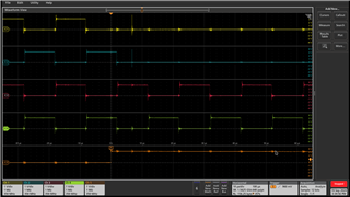
I would like to turn off the EPQM4A, EPWM4B at TBCTR(EPWM4) = 0 and EPWM5A, EPWM5B at TBCTR(EPWM5) = 0. But for now I am not turning off the EPWM 5A and 5B. In the below picture EPWM 4A and EPWM 5A are in phase with each other (but in actual PSFB operation they may not be in phase, but for now in a simple case, I wanted to turn off EPWM 4A and 4B at TBCTR(EPWM4) = 0). When I use the above code I get the below results as shown in the picture.
Channel1 - YELLOW - EPWM4A
Channel2 - BLUE - EPWM4B
Channel3 - RED - EPWM5A
Channel4 - GREEN - EPWM5B
Channel5 - Orange - GPIO (it is set when Vdc_pu1 >410)

When AQCSRFC is used for EPWM 4, 4A goes to zero but 4B goes high that is because 4A and 4B are configured to be complimentary to each other with a dead band of 400ns (a dead band module is used).
I tried to modify the code as below
if(Vdc_pu1 > 410)
{
// FlagEnable.System1 = 0;
GpioDataRegs.GPASET.bit.GPIO2=1;
EPwm4Regs.AQSFRC.bit.RLDCSF = 00;
EPwm4Regs.AQCSFRC.bit.CSFA = 01;
EPwm4Regs.AQCSFRC.bit.CSFB = 01;
EPwm4Regs.DBCTL.bit.POLSEL = 00;
EPwm4Regs.AQCTLA.bit.ZRO = 01;
EPwm4Regs.AQCTLB.bit.ZRO = 01;
}
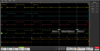
But this give the below results. EPWM4A and EPWM4B are ON for some period and then they turn off.
Channel1 - YELLOW - EPWM4A
Channel2 - BLUE - EPWM4B
Channel3 - RED - EPWM5A
Channel4 - GREEN - EPWM5B
Channel5 - Orange - GPIO (it is set when Vdc_pu1 >410)
So, I would like to know if there is any way to shut down the PWM at a known point of TBCTR=0. Well, the ideal way I would like is to let the PWM finish their ON time, whatever it was, and then TURN OFF after their own period and not turn off for the next period.
I am also attaching the overall code. Please do let me know how can I proceed ahead. I don’t know if using TZFRC of trip zone will help me in turning off the PWM at a known period (as it happens instantaneously).