This thread has been locked.

If you have a related question, please click the "Ask a related question" button in the top right corner. The newly created question will be automatically linked to this question.

TMS320F28379D: how to load application code in my custom board using XDS100V2 DSP EMULATOR

Part Number: TMS320F28379D

Tool/software:

Hi Community,

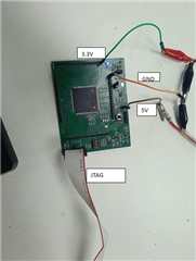
So, lately I've been developing an application using TMS320F28379D launchpad but now as I have developed my application using the launchpad and now I want to integrate my software to the hardware I have built, for the purpose I have bought XDS100V2 DSP EMULATOR but still I don't know how to do that it will be very grateful if anyone from you help me regarding this.

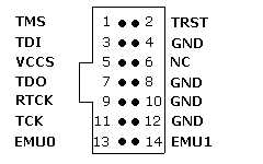
Some question which I already have are that does all the 14-pin JTAG EMULATOR have same pin out???? like I'm using this pinout as my reference but if JTAG pinout for 14-pin JTAG EMULATOR is different from manufacturer to manufacturer than I have to change the configuration.  
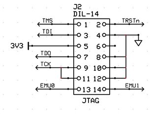
Regards,

Vishwas

  • Hi,

    This picture is of the standard TI 14-pin JTAG header, which should be on the XDS100V2.

    Best Regards,

    Ben Collier

  • Hi Benjamin,

    Thanks for the reply

    As the pinouts are same then why I am not able to load the code in device.

    While reading some other post regarding the same issue I got to know to that I have to download some ftdi drivers libraries to get XDS 100v2 start.

    If it is so, please help me by mentioning them.

    Thanks again,

    Vishwas

  • Hi,

    Could you please take a look at this app note? Please tell me where you get stuck if you cannot resolve your issue. 

    https://www.ti.com/lit/pdf/spracf0

    Best Regards,

    Ben Collier

  • Hi Benjamin,

    This are the schematic of the custom board I have made is there any mistake in this because of which I'm not able to load the code in device.

    Regards,

    Vishwas

  • Hi Ben,

    May be this will give you a proper idea of what I'm doing and maybe you help me with the problem I'm facing.


    This is the screenshot of device manager in which there is texas instrument debug probe section but nothing in com port section is it a matter of concern?

    while testing the connection I got this message

    [Start]

    Execute the command:

    %ccs_base%/common/uscif/dbgjtag -f %boarddatafile% -rv -o -F inform,logfile=yes -S pathlength -S integrity

    [Result]


    -----[Print the board config pathname(s)]------------------------------------

    C:\Users\VISHWA~1.BHA\AppData\Local\TEXASI~1\
    CCS\ccs1280\0\0\BrdDat\testBoard.dat

    -----[Print the reset-command software log-file]-----------------------------

    This utility has selected a 100/110/510 class product.
    This utility will load the adapter 'jioserdesusb.dll'.
    The library build date was 'Jul 24 2024'.
    The library build time was '18:57:55'.
    The library package version is '12.8.0.00189'.
    The library component version is '35.35.0.0'.
    The controller does not use a programmable FPGA.
    The controller has a version number of '4' (0x00000004).
    The controller has an insertion length of '0' (0x00000000).
    This utility will attempt to reset the controller.
    This utility has successfully reset the controller.

    -----[Print the reset-command hardware log-file]-----------------------------

    The scan-path will be reset by toggling the JTAG TRST signal.
    The controller is the FTDI FT2232 with USB interface.
    The link from controller to target is direct (without cable).
    The software is configured for FTDI FT2232 features.
    The controller cannot monitor the value on the EMU[0] pin.
    The controller cannot monitor the value on the EMU[1] pin.
    The controller cannot control the timing on output pins.
    The controller cannot control the timing on input pins.
    The scan-path link-delay has been set to exactly '0' (0x0000).

    -----[The log-file for the JTAG TCLK output generated from the PLL]----------

    There is no hardware for programming the JTAG TCLK frequency.

    -----[Measure the source and frequency of the final JTAG TCLKR input]--------

    There is no hardware for measuring the JTAG TCLK frequency.

    -----[Perform the standard path-length test on the JTAG IR and DR]-----------

    This path-length test uses blocks of 64 32-bit words.

    The test for the JTAG IR instruction path-length failed.
    The JTAG IR instruction scan-path is stuck-at-ones.

    The test for the JTAG DR bypass path-length failed.
    The JTAG DR bypass scan-path is stuck-at-ones.

    -----[Perform the Integrity scan-test on the JTAG IR]------------------------

    This test will use blocks of 64 32-bit words.
    This test will be applied just once.

    Do a test using 0xFFFFFFFF.
    Scan tests: 1, skipped: 0, failed: 0
    Do a test using 0x00000000.
    Test 2 Word 0: scanned out 0x00000000 and scanned in 0xFFFFFFFF.
    Test 2 Word 1: scanned out 0x00000000 and scanned in 0xFFFFFFFF.
    Test 2 Word 2: scanned out 0x00000000 and scanned in 0xFFFFFFFF.
    Test 2 Word 3: scanned out 0x00000000 and scanned in 0xFFFFFFFF.
    Test 2 Word 4: scanned out 0x00000000 and scanned in 0xFFFFFFFF.
    Test 2 Word 5: scanned out 0x00000000 and scanned in 0xFFFFFFFF.
    Test 2 Word 6: scanned out 0x00000000 and scanned in 0xFFFFFFFF.
    Test 2 Word 7: scanned out 0x00000000 and scanned in 0xFFFFFFFF.
    The details of the first 8 errors have been provided.
    The utility will now report only the count of failed tests.
    Scan tests: 2, skipped: 0, failed: 1
    Do a test using 0xFE03E0E2.
    Scan tests: 3, skipped: 0, failed: 2
    Do a test using 0x01FC1F1D.
    Scan tests: 4, skipped: 0, failed: 3
    Do a test using 0x5533CCAA.
    Scan tests: 5, skipped: 0, failed: 4
    Do a test using 0xAACC3355.
    Scan tests: 6, skipped: 0, failed: 5
    Some of the values were corrupted - 83.3 percent.

    The JTAG IR Integrity scan-test has failed.

    -----[Perform the Integrity scan-test on the JTAG DR]------------------------

    This test will use blocks of 64 32-bit words.
    This test will be applied just once.

    Do a test using 0xFFFFFFFF.
    Scan tests: 1, skipped: 0, failed: 0
    Do a test using 0x00000000.
    Test 2 Word 0: scanned out 0x00000000 and scanned in 0xFFFFFFFF.
    Test 2 Word 1: scanned out 0x00000000 and scanned in 0xFFFFFFFF.
    Test 2 Word 2: scanned out 0x00000000 and scanned in 0xFFFFFFFF.
    Test 2 Word 3: scanned out 0x00000000 and scanned in 0xFFFFFFFF.
    Test 2 Word 4: scanned out 0x00000000 and scanned in 0xFFFFFFFF.
    Test 2 Word 5: scanned out 0x00000000 and scanned in 0xFFFFFFFF.
    Test 2 Word 6: scanned out 0x00000000 and scanned in 0xFFFFFFFF.
    Test 2 Word 7: scanned out 0x00000000 and scanned in 0xFFFFFFFF.
    The details of the first 8 errors have been provided.
    The utility will now report only the count of failed tests.
    Scan tests: 2, skipped: 0, failed: 1
    Do a test using 0xFE03E0E2.
    Scan tests: 3, skipped: 0, failed: 2
    Do a test using 0x01FC1F1D.
    Scan tests: 4, skipped: 0, failed: 3
    Do a test using 0x5533CCAA.
    Scan tests: 5, skipped: 0, failed: 4
    Do a test using 0xAACC3355.
    Scan tests: 6, skipped: 0, failed: 5
    Some of the values were corrupted - 83.3 percent.

    The JTAG DR Integrity scan-test has failed.

    [End]

    Regards,

    Vishwas

  • Hi,

    I am seeing in you schematic that there is a net called 'JTAG_TRST' which is different from TRST. What is JTAG_TRST? 

    Also, here is an oscilloscope capture of the start of a Test Connection sequence with XDS100v2: 

    If you have access to an oscilloscope, could you try probing TDO (yellow), TMS (purple), TCK (blue), and TRST (green) as shown below. The screenshot below was captured using the XDS100, and it was a single-capture triggered on the falling edge of TMS. Could you try doing the same and see if your probed signals look the same? 

    Thanks,

    Ben Collier