This thread has been locked.

If you have a related question, please click the "Ask a related question" button in the top right corner. The newly created question will be automatically linked to this question.

TMS320F28378S: Output ADC clock to the GPIO pin.

Part Number: TMS320F28378S
Other Parts Discussed in Thread: SYSCONFIG

Tool/software:

I am looking for a way to configure GPIO pin to output ADCCLK for testing and debugging.

I think there is a way to configure GpioCtrlRegs.GPAMUX1 for this but I am using sysconfig tool and not finding any setting there to configure my GPIO for ADCCLK out.

Any help on this issue is greatly appreciated.

  • Hi Valeriy,

    ADCCLK cannot be brought out of the device.  ADCCLK is SYSCLK divided by the ADC clock prescaler in register ADCCTL2.PRESCALE.  You can bring out SYSCLK  though through XCLKOUT pin using below function calls:

        SysCtl_selectClockOutSource(SYSCTL_CLOCKOUT_SYSCLK);

        SysCtl_setXClk(SYSCTL_XCLKOUT_DIV_8);

        GPIO_setPinConfig(GPIO_73_XCLKOUT);

    Routine above will output the 200MHz  SYSCLK in GPIO73 as 200MHz/8 (25MHz) since 200MHz cannot pass directly to a GPIO.  It has to be prescaled to a lower frequency in order not to be attenuated.

    Regards,

    Joseph

  • Joseph,

    I followed your instructions and got a pretty unstable clock output. 

    I also misunderstood my requirements. I do not need to have specifically ADCCLK on the output, just need to have 4Mhz frequency output on a specific GPIO that is not GPIO73 (GPIO94 in my case).

    Which system should I use to generate stable clock of 4.096 Mhz frequency?

    Thanks.

  • Hi Valeriy,

    There are several options you can try in generating that clock.  One would be to use timer (see example  timer_ex1_cputimers) by modifying the timer period and add a GPIO toggle to output the frequency you want.  Another would be to use the EPWM module to generate an output.  See example epwm_ex2_updown_ac.

    Regards,

    Joseph

  • Joseph.

    I have tried the first option you suggested by using the timer and could not get the frequency much above 500kHz. I am wondering if I missed some clock setting to make it go faster or it is getting to the limit of what C2000 can do?

  • Valeriy,

    There may be too much software overhead between entering the timer ISR, servicing it and changing the state of the GPIO pin.  I suggest you try the EPWM method since the PWM has the ability to accurately control the switching of the PWM output pin without looping through software.  The PWM counters and time base period can effectively define the toggling frequency for you.  The EPWM can be clocked at maximum speed of 100MHz and there are several prescale options you can set.  This together with time base period setting TBPRD) and counter compare settting (CMPx) should be able to get you to have exactly 4.096MHz.  I suggest that you experiment with  epwm_ex2_updown_ac on one EPWM by modifying the prescalers, TBPRD and CMPx values to see how this affects the EPWM output switching rate.

    Regards,

    Joseph

  • Joseph,

    It was pretty easy to configure ePWM to output 4Mhz clock, but only out of one of the ePWM enabled pins. Is there any way to route this signal to other GPIOs internally? Can output X-BAR do that?

    Thanks.

  • Valeriy,

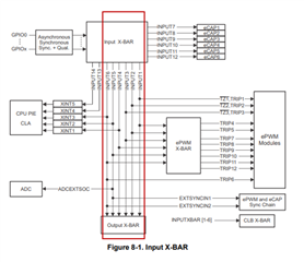
    Yes, you can use the crossbar for this purpose.  What you can do is configure the input crossbar to use any toggling GPIO from your EPWM test to connect to any of INPUT1-6 as these go directly to output crossbar.  Configure also the output crossbar to route the signal to any of the GPIOs but ensure the target GPIO to use is configured as output.

    Regards,

    Joseph

  • Joseph,

    Please clarify if I can configure output crossbar to route the signal to any of the GPIO or only to GPIO where output crossbar is enabled. The port I would like to use is GPIO94 but not sure if it is possible: GPIO Muxed Pins

  • Valeriy,

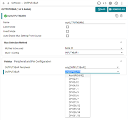
    Yes, you should be able to.  I forgot to attach some useful diagrams to illustrate this.  See below:

    Regards,

    Joseph

  • Josef,

    I was able to connect my signals all the way through to the output X-bar just like you show on your pictures. I am stuck looking for the ways to route signal from output X-bar to the GPIO94. This pin does not explicitly indicate that it has OUTPUTXBAR capability (see GPIO Muxed Pins link in my post above). 

  • Valeriy,

    Sorry i did not realize that in F2837xS, you're only limited to route the signal on the GPIOs enumerated in the picture from the output XBAR mux.

    Regards,

    Joseph

  • Thank you for confirmation.

    I was afraid I was missing something.