TMS320F2800157: DAC To ADC Loopback Test on TMS320F2800157

Part Number: TMS320F2800157
Other Parts Discussed in Thread: C2000WARE

Tool/software:

Hello, 

I am working on C2000 real-time MCU Safety Mechanisms where I came across ADC to DAC loopback test on the TMS320F2800157 microcontroller.

I want to implement the DAC to ADC loopback test where I can satisfy these requirements:

1- The software shall verify correct ADC conversion for the used channels from the following ADC channels ADCIN0..ADCIN20.
2. The software shall verify correct ADC conversion by performing an ADC-DAC loopback test.
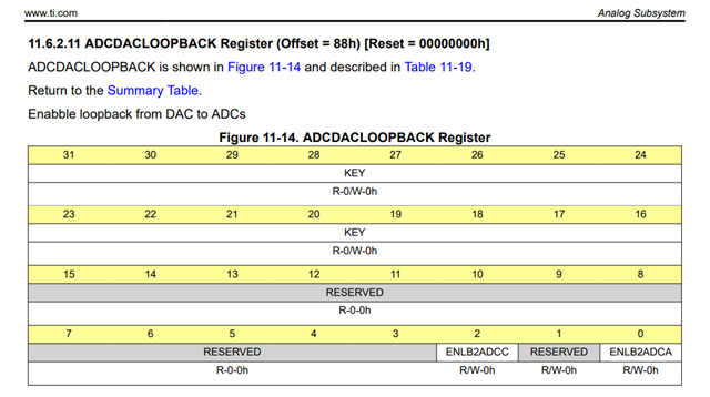
3. The software shall perform an ADC-DAC loopback test by Enabling loopback mode using ADCLOOPBACK.ENLB2ADCA and ADCLOOPBACK.ENLB2ADCC.
4. The software shall Set INTERNALTESTCTL.TESTSEL to 0x5 and ensuring minimum sampling window size (ACQPS)is more than 4.27 μs.
5. The software shall Configure the CMPSS1 DAC to supply known voltages to the ADC and verifying the conversion results.
6. The software shall Clear the ADCLOOPBACK.ENLB2ADCA and ADCLOOPBACK.ENLB2ADCC bits after the test.
7. The software shall execute [TBD] in case of incorrect ADC conversion detected.

I want  to know what approach or steps should I be taking to implement this or if there any example that implement this I can look at



  • Hi Mazen,

    Unfortunately, we do not have any examples for this.

    Please refer to section 12.13.7 ADC-DAC Loopback Testing in TMS320F280015x Real-Time Microcontrollers Technical Reference Manual (Rev. B)

    Let me know if you have further questions.

    Thanks,

    Susmitha

  • I looked at the section but this only theoretically answers the questions. I want to know what approach should I take to implement this test. For example, do I first intialize the cmpss dac and then the adc and then enable the loopback test in the corresponding register etc...

    Also. I don't understand the concept very much. I noticed there are two comparators, one is high and one is low but when I configure the dac to set a digital value to be converted, why is there DACHVALS and DACVALS and when do I use either. I understand from this safety test that I want to configure the DAC and set a certan digital value in which the DAC will convert to an analog signal and by enabling the ADCLOOPBACK register bits this loopback signal will be fed into the adc. The output then of the adc is a digital value in which I will compare it with the dacval. if they are the same the test passed. 

    I now don't undertsand why are there low and high dacval and why do I need the comparator. i only need the dac for the test.

  • Hi Mazen,

     If you want to have a loopback test on DAC, you simply have to program the DAC registers to output a voltage and convert this voltage through the ADC channels corresponding to the DAC that you are programming.  Let me know if this works for you.

    In section 12.13.7 ADC-DAC Loopback Testing, you just need to enable loopback from analog subsystem. Attached is the related register. when you enable that, then the adc is going to sample the dac output of CMPSS regardless of adc channel selection.

    Please use CMPx_DACL for DAC.

    Thanks,

    Susmitha

  • Hi Mazen,

    Please also refer to Optional DAC Addition in below document. This might help.

     ADC Lab (ti.com)

    The software is available in C2000Ware "training" folder - it's the ADC Lab. Here is the link

    [C2000Ware_Install_Path]/training/device/[device_name]/analog_subsystems/lab_adc

    Thanks,

    Susmitha

  •  // Enable CMPSS1 module
        EALLOW;

        Cmpss1Regs.COMPDACHCTL.bit.SWLOADSEL = 0; // system clock used
        Cmpss1Regs.COMPDACLCTL.bit.DACSOURCE = 0; //Source Dac to be from DACLVALS instead of Ramp generator

        Cmpss1Regs.DACLVALS.bit.DACVAL = 0xFFF;

        AnalogSubsysRegs.CMPSSCTL.bit.CMP1LDACOUTEN = 0; // CMPSS1.COMPL is enabled and associated DAC will act as reference for comparator
        AnalogSubsysRegs.CMPSSCTL.bit.CMPSSCTLEN = 1; // Rest of the configuration in this register are enabled

        EDIS;

    This is my code for initializing the DAC in the cmpss? is there something missing? I also have a function for enabling ADCDACLOOPBakc and one for disabling. Let's conside these functions. I now have a perform test in which I will call the init dac then enable loopback and then read the result from the adc channel and compare it with dacval. Is this correct?

    I also have another question. What will the dac output be output to? which channel in the adcca or addcc will I read the adc conversion value? or where can I configure it?
  • Hi Mazen,

    Yes, the code looks good, and your understanding is right.

    Dac output can be outputted to A0/C15.The DAC output is sampled directly on an internal analog channel. There should be no need to configure the pinmux in this case. This information can be found from Table 6-16. Analog Pins and Internal Connections of datasheet.

     Please try this and let me know if you have further questions.

    Thanks,

    Susmitha

  • Is there anything I need to be doing to trigger the adc sampling? My code does the following:

    function 1: 

    1- COMPCTL.bit.COMPDACE = 1
    2- 
    COMPDACHCTL.bit.SWLOADSEL = 0;
    3- 
    COMPDACLCTL.bit.DACSOURCE = 0;
    4- 
    DACLVALS.bit.DACVAL = 0xFFF
    5. 
    AnalogSubsysRegs.CMPSSCTL.bit.CMP1LDACOUTEN 0; 
    6. 
    AnalogSubsysRegs.CMPSSCTL.bit.CMPSSCTLEN = 1;

    this is used to initialize the dac

    function 2:

    1-
    ADCDACLOOPBACK.all =  0xA5A50001;

    This is to enable adcloopbacktest

    I also initialize clock to the cmpss1 register using:

    CpuSysRegs.PCLKCR14.bit.CMPSS1 = 1;


    when I read the adc value in adca channel 0 the value of the result is 0 through register  
    AdcaResultRegs.ADCRESULT0. Am I missing something or is something more needs to be configured?

  • Hi Mazen,

    Yes, ADC has to be triggered. Please use ADC_setupSOC to configure SOC and trigger.

    There are examples in C2000ware on how to setup ADC SOC for Sampling.

    [C2000Ware_Install_Path]/driverlib\f280015x\examples\adc

    Thanks,

    Susmitha

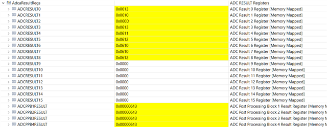
  • The test is now working according to the configurations we mentioned. However, the result of the adc is store in the following registers and not only in the result register of channel 0 and I do not want this because this affects other areas of the code. Is this the normal operation of the dac loopback test or can it be configured to only store the value in adcresult0

  • Hi Mazen,

    How is the ADC SOC setup? Please setup SOC with ADC channel accordingly.

    For example, if you configure SOC5, SOC6, SOC7, you get results stored in ADCRESULT5, ADCRESULT6, ADCRESULT7 respectively.

    Thanks,

    Susmitha

  • The ADC SOC is setup for only channel 0 and it writes in all results. Is this the normal? does the dac write the output to all result registers of the module being tested or does it output the result on channel 0 result only

  • Hi Mazen,

    Can you send me how your ADC SOC setup configuration looks like?

    Which SOC did you use?

    Thanks,

    Susmitha

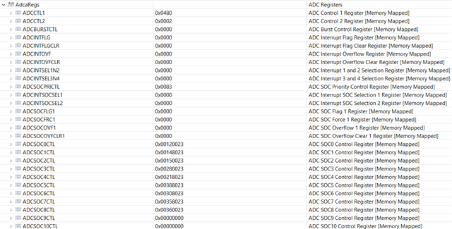
  • SOC Priority = 0x0A in ADCSOCPRICTL Register
    Channel Select of SOC is 0 in ADCSOC9CTL Register
    TrigSeL bits are 0x03 which is cputimer2

    ACQPS is 0x11 + 0x12

  • Hi Mazen,

    I see you are using SOC9 .... Can you change to SOC0 if possible and see if issue is still happening?

    Thanks,

    Susmitha

  • I tried SOC 0 but all registers are still being written to of the ADCRESULTS Registers

  • Hi Mazen,

    Can you try configuring to disable ADCBURSTCTL Register? This will stop multiple SOCs to run.

    Meanwhile I will check with other experts, if it is common to see such.

    Thanks,

    Susmitha

  • The problem has not yet been resolved. Just to clarify, the DAC to ADC Loopback test has been working but I want to solve the problem of when the DAC outputs adc signal teh ADC then samples this signal and outputs the result to several Result Registers and this conflicts with the implementation I am tryng to do I only want the ADC to output this on just one adc result register which is ADCRESULTREGISTER0 as the SOC used is SOC0 

  • Hi Mazen,

    On checking with experts, result should only appear in the corresponding register and not in all result registers.

    You can send me the entire project here; I will try to replicate it on my end.

    Thanks,

    Susmitha

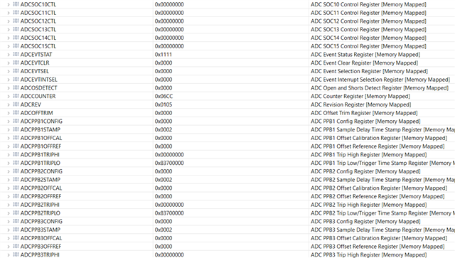
  • The following are screenshots from the register configurations:

    and the following is a screenshot from the result registers when doing the dac test:

  • Hi Mazen,

    What is other SOC configured to?

    Above register info will not help me to replicate the issue. It would be great to have entire project files to reproduce here on my end.

    Thanks,

    Susmitha

  • Hello Susmitha,

    I am working with Mazen and I also have the same issue.

    We can't share the entire project as it's confidential with respect to our customer.

    But I can share more info with you regarding the configuration of the ADC.

    • We are using External VREF and configured it using AnalogSubsysRegs.ANAREFCTL.bit.ANAREFSEL = 1
    • We are using both ADCA and ADC but we only perform the DAC loopback test on ADCA and ADCC isn't affected by the test.
    • In ADCA we are using SOC0 to SOC8.
    • Our acquisition window for all SOCs is 35
    • ADC Clock is 50MHZ, we are using a pre-scaler /2.
    • SYS Clock is 100MHZ.
    • Al the SOCs trigger sources are timer based.
    • We are using TIMER0 at 20us, TIMER1 at 100us and TIMER2 at 1ms.
    • No interrupts are used for the ADC the result registers are read in the corresponding TIMER.

    For SOCs to Channel mapping we have the following 

    1. SOC0 -> CH4 -> Triggered by TIMER0
    2. SOC1 -> CH9 -> Triggered by TIMER0
    3. SOC2 -> CH10 -> Triggered by TIMER0
    4. SOC3 -> CH16 -> Triggered by TIMER1
    5. SOC4 -> CH3 -> Triggered by TIMER1
    6. SOC5 -> CH17 -> Triggered by TIMER2
    7. SOC6 -> CH1 -> Triggered by TIMER2
    8. SOC7 -> CH11 -> Triggered by TIMER2
    9. SOC8 -> CH12 -> Triggered by TIMER2

    For the DAC configuration as Mazen mentioned before we have the following configuration

    • Channel Select of DAC SOC9 is CH0 in ADCSOC9CTL Register
    • Trigger is TIMER2(1ms)
    • ACQPS is the same as the rest of the SOCs

    I think these configurations is more than enough describing all the details needed to reproduce the issue.

    Kindly note that the ADC configurations has been tested and working in our project for an entire year now, and this DAC to ADC test is crucial and blocking our development.

  • Hello,

    While the ADC/DAC loopback mode is enabled, any SOC that is triggered will sample the DAC. If you trigger SOC5, it will sample the DAC and store the result in the ADCxRESULT5 register, regardless of what channel SOC5 is configured for. If you trigger SOC7, it will sample the DAC and store the result in the ADCxRESULT7 register, regardless of what channel SOC7 is configured for. To avoid getting results in multiple result registers, make sure to disable triggers to all SOCs except the one you wish to use for the loopback test. The triggers can then be re-enabled after the loopback mode has been turned off.

    Best regards,
    Ibukun

  • Thank you for your response this helped. 

    Just another question, the Safety Manual doesn't specify whether or not the DAC to ADC loopback test should be ran in startup or also in runtime.

    So is it enough to run the test in startup? will this satisfy the safety mechanism? 

  • Hi Hanna,

    DAC to ADC loopback test can be run in either startup or in runtime. It will work either way.

    Please let me know if you have any further questions. If not, please go ahead and close the thread.

    Thanks,

    Susmitha

  • Hi Susmitha,

    I know that it can be run in either startup or runtime but my question is will running it only in the startup fulfill that the safety mechanism is implemented? 

  • Hi Hanna,

    You'd normally do this at startup only. 

    Thanks,

    Susmitha

  • Running DAC to ADC Loopback test at startup only does satisfy the safety mechanism.