This thread has been locked.

If you have a related question, please click the "Ask a related question" button in the top right corner. The newly created question will be automatically linked to this question.

LAUNCHXL-F280039C: F280039C and DRV8323RS - moduleOverCurrent trip with lab 2

Part Number: LAUNCHXL-F280039C
Other Parts Discussed in Thread: BOOSTXL-DRV8323RS

Tool/software:

I am using the following boards with the universal_motorcontrol_lab_f28003x software...

  • LAUNCHXL-F280039C
  • BOOSTXL-DRV8323RS

I have completed lab 1 which passed all the tests.

I am now running lab 2, but when I set flagEnableRunAndIdentify I get a module over current trip (motorVars_M1.faultMtrPrev.bit.moduleOverCurrent).

I have configured the boards as shown in section 3.2.2 (LAUNCHXL-F280039C Setup) and section 3.2.10 (BOOSTXL-DRV8323RS Setup) of the User's Guide for Motor Control SDK Universal Project and Lab.

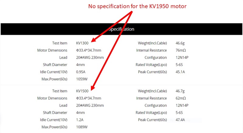
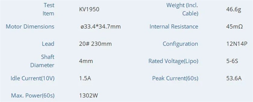
I am using the following motor....

store.tmotor.com/.../f90-fpv-motor.html

Unfortunately there is very little data specified for this motor, so I am using the definitions for Drone_DJI920KV.

I tried changing parameters USER_MOTOR1_Rs_Ohm, USER_MOTOR1_VOLT_MAX_V and USER_MOTOR1_OVER_CURRENT_A but still get an overcurrnet.

How do I fix this overcurrent fault, why is it happening ?

#elif (USER_MOTOR1 == Drone_DJI920KV)
// Refer to the description of the following parameters for Teknic_M2310PLN04K
#define USER_MOTOR1_TYPE                   MOTOR_TYPE_PM
#define USER_MOTOR1_NUM_POLE_PAIRS         (7)
#define USER_MOTOR1_Rr_Ohm                 (NULL)
#define USER_MOTOR1_Rs_Ohm                 (0.04f)//(0.115332372f)
#define USER_MOTOR1_Ls_d_H                 (1.76480826e-05f)
#define USER_MOTOR1_Ls_q_H                 (1.76480826e-05f)
#define USER_MOTOR1_RATED_FLUX_VpHz        (0.00605002558f)
#define USER_MOTOR1_MAGNETIZING_CURRENT_A  (NULL)
#define USER_MOTOR1_RES_EST_CURRENT_A      (3.0)
#define USER_MOTOR1_IND_EST_CURRENT_A      (-2.5)
#define USER_MOTOR1_MAX_CURRENT_A          (20.0)
#define USER_MOTOR1_FLUX_EXC_FREQ_Hz       (120.0)
#define USER_MOTOR1_NUM_ENC_SLOTS          (1000)       // N/A
#define USER_MOTOR1_INERTIA_Kgm2           (5.06154e-06)

#define USER_MOTOR1_FREQ_NEARZEROLIMIT_Hz  (5.0f)          // Hz

#define USER_MOTOR1_RATED_VOLTAGE_V        (12.0)
#define USER_MOTOR1_FREQ_MIN_Hz            (10.0)          // Hz
#define USER_MOTOR1_FREQ_MAX_Hz            (2000.0)        // Hz

#define USER_MOTOR1_FREQ_LOW_Hz            (10.0)          // Hz
#define USER_MOTOR1_FREQ_HIGH_Hz           (1200.0)        // Hz
#define USER_MOTOR1_VOLT_MIN_V             (3.0)           // Volt
#define USER_MOTOR1_VOLT_MAX_V             (30)   //(12)       // Volt

#define USER_MOTOR1_FORCE_DELTA_A          (0.05)          // A
#define USER_MOTOR1_ALIGN_DELTA_A          (0.01)          // A
#define USER_MOTOR1_FLUX_CURRENT_A         (0.5)           // A
#define USER_MOTOR1_ALIGN_CURRENT_A        (1.0)           // A
#define USER_MOTOR1_STARTUP_CURRENT_A      (3.0)           //
#define USER_MOTOR1_TORQUE_CURRENT_A       (2.0)           // A
#define USER_MOTOR1_OVER_CURRENT_A         (30)          //(16.5)

#define USER_MOTOR1_SPEED_START_Hz         (20.0f)
#define USER_MOTOR1_SPEED_FORCE_Hz         (20.0)
#define USER_MOTOR1_ACCEL_START_Hzps       (10.0f)
#define USER_MOTOR1_ACCEL_MAX_Hzps         (100.0f)

#define USER_MOTOR1_SPEED_FS_Hz             (3.0f)

// only for encoder, no available on this motor
#define USER_MOTOR1_ENC_POS_MAX            (USER_MOTOR1_NUM_ENC_SLOTS * 4 - 1)
#define USER_MOTOR1_ENC_POS_OFFSET         (668)

// Only for eSMO
#define USER_MOTOR1_KSLIDE_MAX             (0.55f)
#define USER_MOTOR1_KSLIDE_MIN             (0.10f)

#define USER_MOTOR1_PLL_KP_MAX             (7.25f)
#define USER_MOTOR1_PLL_KP_MIN             (1.75f)
#define USER_MOTOR1_PLL_KP_SF              (20.0f)
#define USER_MOTOR1_PLL_KI                 (2.8125E-06f)    // Not used, reserve

#define USER_MOTOR1_BEMF_THRESHOLD         (0.5f)
#define USER_MOTOR1_BEMF_KSLF_FC_SF        (1.0f)
#define USER_MOTOR1_THETA_OFFSET_SF        (1.0f)
#define USER_MOTOR1_SPEED_LPF_FC_Hz        (200.0f)

// for IS-BLDC
#define USER_MOTOR1_RAMP_START_Hz           (5.0f)
#define USER_MOTOR1_RAMP_END_Hz             (30.0f)
#define USER_MOTOR1_RAMP_DELAY              (1)

#define USER_MOTOR1_ISBLDC_INT_MAX          (0.015f)
#define USER_MOTOR1_ISBLDC_INT_MIN          (0.010f)

// for Rs online calibration
#define USER_MOTOR1_RSONLINE_WAIT_TIME      (60000U)    // 5min/300s at 5ms base
#define USER_MOTOR1_RSONLINE_WORK_TIME      (24000U)     //2min/120s at 5ms base

// Current and Speed PI Regulators Tuning Coefficient
#define USER_MOTOR1_GAIN_SPEED_LOW_Hz        (60.0f)
#define USER_MOTOR1_GAIN_SPEED_HIGH_Hz       (150.0f)

#define USER_MOTOR1_KP_SPD_START_SF          (1.5f)       // 0.1~100.0
#define USER_MOTOR1_KI_SPD_START_SF          (1.5f)       // 0.1~10.0

#define USER_MOTOR1_KP_SPD_LOW_SF            (2.0f)       // 0.1~100.0
#define USER_MOTOR1_KI_SPD_LOW_SF            (2.0f)       // 0.1~10.0

#define USER_MOTOR1_KP_SPD_HIGH_SF           (1.0f)       // 0.1~100.0
#define USER_MOTOR1_KI_SPD_HIGH_SF           (1.0f)       // 0.1~10.0

#define USER_MOTOR1_GAIN_IQ_LOW_A            (2.0f)
#define USER_MOTOR1_GAIN_IQ_HIGH_A           (6.0f)

#define USER_MOTOR1_KP_IQ_START_SF           (1.5f)       // 0.1~10.0
#define USER_MOTOR1_KI_IQ_START_SF           (1.5f)       // 0.1~10.0

#define USER_MOTOR1_KP_IQ_LOW_SF             (2.0f)       // 0.1~10.0
#define USER_MOTOR1_KI_IQ_LOW_SF             (2.0f)       // 0.1~10.0

#define USER_MOTOR1_KP_IQ_HIGH_SF            (1.0f)       // 0.1~10.0
#define USER_MOTOR1_KI_IQ_HIGH_SF            (1.0f)       // 0.1~10.0

#define USER_MOTOR1_KP_ID_SF                 (1.0f)       // 0.1~10.0
#define USER_MOTOR1_KI_ID_SF                 (1.0f)       // 0.1~10.0

  • Hello,

    An Overcurrent fault is typically due to bad motor parameters- as you said, you don't have much data on this motor. You have a couple of options here:

    1. Build level 2 requires good values for the motor's basic parameters and very good values for USER_MOTOR1_FREQ_LOW_Hz, USER_MOTOR1_FREQ_HIGH_Hz, USER_MOTOR1_VOLT_MIN_V, and USER_MOTOR1_VOLT_MAX_V. Adjusting these values according to experimentation and motor specs will allow you to continue at this build level.

    2. If this information is not known, then moving on to build level 3 is sometimes helpfulif you have good values for basic motor parameters.

    3. If basic motor parameters are not known or build level 3 is also not working, skipping to build level 4 for the purpose of using the Motor Identification routine may be necessary. See the user's guide for further information on that process.

    Regards,
    Jason Osborn

  • Thanks Jason

    I tried build level 3 and the motor span, although it ran a bit rough and had very little torque (presumably because the motor parameters are wrong ?) . 

    So I tried build level 4, the motor did some twitching and then began to spin but I dont think it completed the calibration.  

    How can you tell if the calibration has successfully completed ?

    I looked at the faults and the flags were set for 'startupFailed' and 'currentUnbalance', so I assume it failed ?

    I have tried changing some of the motor parameters but now it fails on 'moduleOverCurrent' again.

    I thought InstaSPIN FOC was supposed to calibrate the motor without having to know all these parameters ? 

    This is a crucial requirement, because there are little or no specifications for the motors I will be using.

    Is InstaSPIN supposed to solve this issue, or have I misunderstood ?

    Also in the user guide for build level 4, it talks about an AC source but I dont know what this is referring to...

    3.5.4.3 Run the code

    1. Set the AC source output to 0 V at 50/60Hz, turn on the AC power supply, slowly increase the input voltage from 0-V to 220-V AC

    Build level 4 states that these parameters are required, but I only know the the following parameters...

    #define USER_MOTOR1_TYPE MOTOR_TYPE_PM 
    #define USER_MOTOR1_NUM_POLE_PAIRS (7) // 12N14P configuration
    #define USER_MOTOR1_Rs_Ohm (0.062) // this is for the KV1500 motor (its not specified for the KV1950 motor)

    In fact the phase resistance is not quite correct, because the value is for a motor with a lower KV rating (theres no specifications for the KV1950 motor).

    I don't know the following parameters (or any of the other parameters defined in user_mtr1.h)...

    #define USER_MOTOR1_Rr_Ohm 
    #define USER_MOTOR1_Ls_d_H 
    #define USER_MOTOR1_Ls_q_H 
    #define USER_MOTOR1_RATED_FLUX_VpHz

    How can I proceed, or is it not possible without knowing all the motor parameters ?

    Below are the only motor specifications available, in fact there are no specifications for the KV1950 version...

    store.tmotor.com/.../f90-fpv-motor.html

  • I contacted the motor manufacture to get the specs for the KV1950 version (see image below).

    I have found out that this motor is delta wound.  Does the software and InstaSPIN work with delta wound motors ?

    I also asked the manufacture about the phase resistance.  They said that the 'internal resistance' is measured between 2 of the motor wires (there are 3 wires in total).  They also said that to get the phase resistance, the internal resistance has to be multiplied by 1.5.  Therefore the phase resistance would be 67mR (i.e. 45mR x 1.5)

    The following parameters are the only ones I've been able to determine (not sure if I have calculated them all correctly):

    • USER_MOTOR1_Rs_Ohm = 0.067
      • Internal Resistance of 45mR (measured between two wires)
      • Motor is delta wound, therefore stator resistance is 45mR * 1.5 = 67mR
    • USER_MOTOR1_RATED_FLUX_VpHz = 0.002537803
      • Back EMF is 1V at 1950rpm
      • Therefore back EMF is 0.5128V at 1000rpm (1000rpm/1950rpm)
      • Rated flux = Back EMF * 60 * 1/1000 * 1/PolePair * 1/√3
      • Rated flux = 0.5128 * 60 * 1/1000 * 1/7 * 1/√3
      • Rated flux = 0.002537803
    • USER_MOTOR1_MAX_CURRENT_A = 53.6
      • Motor peak current rating is 53.6A
    • USER_MOTOR1_RATED_VOLTAGE_V = 22.2
      • Motor voltage rating is 5S-6S
      • 3.7V x 6 = 22.2V
    • USER_MOTOR1_FREQ_MAX_Hz = 3500
      • Max frequency = (Max rpm * Total Poles) / 120
      • Max frequency = (30,000 * 14) / 120
      • Max frequency = 3500

    Even with these updated parameters, InstaSPIN does not seem to characterise the motor (for build level 4).

    During the calibration the motor eventually begins to twitch, then slowly spins, but then stops spinning before the calibration is completed (the pwm frequency can be heard to increase in the motor). Fault flags indicate 'startupFailed', 'currentUnbalance' and ‘moduleOverCurrent’ faults.

  • Referring to this e2e thread, there is no change in requirements for wye vs delta configuration- except that the estimated values (which should be correct for FAST) will not exactly match the specs provided by the manufacturer. 

    Referring to the following image:

    Do the parameters with comments in your user motor .h file match the provided specifications? These are used in the identification process.

    Regards,
    Jason Osborn

  • Hi Jason

    I have calculated some of the parameters based on the information shown on the motor manufacturer's website:

    • The peak current is specified as 53.6A (for 60 seconds)
    • The maximum motor speed is around 30,000rpm (from the test results with various propellers fitted) 

    1. USER_MOTOR1_FREQ_MAX_Hz - have I calculated this correctly (see below) ?

    Max frequency = [(Max rpm * Total Poles) / 120] = [(30,000 * 14) / 120] = 3,500 Hz

    2. USER_MOTOR1_NUM_ENC_SLOTS - this is not applicable as there is no encoder position sensor fitted to the motor

    3. USER_MOTOR1_INERTIA_Kgm2 - I don't have this information

    The value of the parameters are shown below:

    #define USER_MOTOR1_MAGNETIZING_CURRENT_A  (NULL)
    #define USER_MOTOR1_RES_EST_CURRENT_A      (5.4) // 10~30% of rated current of the motor i.e. 53.6A x 10% = 5.4A
    #define USER_MOTOR1_IND_EST_CURRENT_A      (-5.4)// 10~30% of rated current of the motor i.e. 53.6A x 10% = 5.4A
    #define USER_MOTOR1_MAX_CURRENT_A          (5.4) // 10~30% of rated current of the motor i.e. 53.6A x 10% = 5.4A
    #define USER_MOTOR1_FLUX_EXC_FREQ_Hz       (350) // 10~30% of rated frequency of the motor i.e. 3500 x 10% = 350Hz
    #define USER_MOTOR1_NUM_ENC_SLOTS          (1000)       // N/A (sensorless)
    #define USER_MOTOR1_INERTIA_Kgm2           (5.06154e-06) // unknown
    #define USER_MOTOR1_FREQ_MAX_Hz            (3500) // Max frequency = [(Max rpm * Total Poles) / 120] = [(30,000 * 14) / 120] = 3,500 Hz

  • FAST: In case you missed in in the documentation and it happens to be relevant, FAST identification is meant for a motor that is NOT coupled with a load- i.e. free spinning.

    Inertia: In this context, because motor dimensions and weight are both given by the manufacturer, we should be able to calculate an inertia value that looks better. Ideally, we're only accounting for the weight that is coupled tightly to the rotating axis, but the number should be close.

    Moment of inertia of a solid cylinder (the rotor) is mathematically defined as:

    • Inertia = (mass * radius^2 / 2)
    • = (46.6g * (4mm/2)^2)/2
    • = 9.32×10^-8 kg m^2 (notice the unit conversion!)
      • For the code, that's 9.32e-08 if you're keeping the format consistent.

    Because your motor is very small, that seems right to me. Adjust your inertia value and let me know if this improves performance at all. The actual inertia value will be somewhat lower than this (as this is not only the mass tightly coupled to the rotor), but this should be a better starting point than the default.

    Regards,
    Jason Osborn

  • As a side note, I had not considered it before just now, but low inductance motors require slight adjustment for motor ID to work. Consider the following steps:

    This user's guide is a little bit outdated in regards to the format of the parameters (note the units on any parameter it discusses) but it is conceptually correct.

    Regards,
    Jason Osborn

  • Thanks Jason

    The motor is not coupled to anything, it is free spinning.

    I have used the inertia you calculated, but the calibration does not run because I instantly get a moduleOverCurrent fault.

    The inertia you calculated uses the complete weight of the motor, should it not use the weigh of the rotor only (which is not specified so therefore unknown) ?

    Below are the parameters I used...

    #define USER_MOTOR1_TYPE                   MOTOR_TYPE_PM
    #define USER_MOTOR1_NUM_POLE_PAIRS         (7)
    #define USER_MOTOR1_Rr_Ohm                 (NULL)
    #define USER_MOTOR1_Rs_Ohm                 (0.067f)//(0.115332372f)  Internal Resistance of 45mR.  Stator resistance is 45mR * 1.5 = 67mR (delta winding)
    #define USER_MOTOR1_Ls_d_H                 (1.76480826e-05f)
    #define USER_MOTOR1_Ls_q_H                 (1.76480826e-05f)
    #define USER_MOTOR1_RATED_FLUX_VpHz        (0.002537803f) // 1V at 1950rpm, therefore 0.5128V at 1000rpm (1000rpm/1950rpm). Flux = 0.5128 * 60 * 1/1000 * 1/PolePair * 1/√3 = 0.5128 * 60 * 1/1000 * 1/7 * 1/√3 = 0.002537803
    
    #define USER_MOTOR1_MAGNETIZING_CURRENT_A  (NULL)
    #define USER_MOTOR1_RES_EST_CURRENT_A      (3) // 10~30% of rated current of the motor i.e. 53.6A x 10% = 5.4A
    #define USER_MOTOR1_IND_EST_CURRENT_A      (-2.5)// 10~30% of rated current of the motor i.e. 53.6A x 10% = 5.4A
    #define USER_MOTOR1_MAX_CURRENT_A          (20) // 10~30% of rated current of the motor i.e. 53.6A x 10% = 5.4A
    #define USER_MOTOR1_FLUX_EXC_FREQ_Hz       (350) // 10~30% of rated frequency of the motor i.e. 3500 x 10% = 350Hz
    #define USER_MOTOR1_NUM_ENC_SLOTS          (1000)       // N/A (sensorless)
    #define USER_MOTOR1_INERTIA_Kgm2           (9.32e-08) // Inertia = (mass * radius^2 / 2).  Inertia =  (46.6g * (4mm/2)^2)/2 =  9.32×10^-8 kg m^2 (notice the unit conversion!)
    #define USER_MOTOR1_FREQ_MAX_Hz            (3500) // Max frequency = [(Max rpm * Total Poles) / 120] = [(30,000 * 14) / 120] = 3,500 Hz
    

  • Thanks Jason,

    I started to read section 6.10.1.8.1 (Identifying Low Inductance PMSM Motors).

    I understand the part about changing the potential divider resistor or the voltage feedback to maximum number of bits of the ADC converter and the parameter USER_ADC_FULL_SCALE_VOLTAGE_V (which is actually USER_M1_ADC_FULL_SCALE_VOLTAGE_V in the software).

    But I cant find any of the following parameters (or similar) in the software which are mentioned in the manual:

    • USER_IQ_FULL_SCALE_VOLTAGE_V 
    • USER_R_OVER_L_EST_FREQ_Hz
    • USER_MOTOR_FLUX_EST_FREQ_Hz
    • USER_IQ_FULL_SCALE_VOLTAGE_V no longer exists. The advice mentioned for this parameter can be ignored for now.
    • USER_R_OVER_L_EST_FREQ_Hz corresponds to USER_M1_R_OVER_L_EXC_FREQ_Hz.
    • USER_MOTOR_FLUX_EST_FREQ_Hz corresponds to USER_MOTOR1_FLUX_EXC_FREQ_Hz.

    Additionally, just to confirm- is this motor intended for use in a racing drone, as described in the original link you posted?

    Regards,
    Jason Osborn

  • In case its of any help, I have captured scope traces of the phase voltage and current when running lab 2 which causes the moduleOverCurrent fault.

    Phase A voltage and current

    Phase B voltage and current

    Phase C voltage and current

    Phase ABC voltage and phase A current