This thread has been locked.

If you have a related question, please click the "Ask a related question" button in the top right corner. The newly created question will be automatically linked to this question.

TMS320F280039C: Problem in manually controlling SPISTE pin

Part Number: TMS320F280039C
Other Parts Discussed in Thread: SYSCONFIG

Tool/software:

Im using the spi_ex3_external_loopback example and modified it so that Im only transmitting 16 bytes of data on SPIB wit the SPISTE pin controlled manually. Here is the code:

//
// Included Files
//
#include "driverlib.h"
#include "device.h"
#include "board.h"
#include "f28003x_device.h"


//
//Macros
//
static inline void GPIO_SPI_FLASH_CS_CLEAR(void){
    GpioDataRegs.GPACLEAR.bit.GPIO15 = 1;
}

static inline void GPIO_SPI_FLASH_CS_SET(void)
{
    GpioDataRegs.GPASET.bit.GPIO15 = 1;
}

//
//Prototype
//
uint16_t spi_transmit_byte(uint16_t data_tx);

//
// Main
//
void main(void)
{
    uint16_t i;

    uint16_t TxData_SPIB[] = {0x10, 0x11, 0x12, 0x13, 0x14, 0x15, 0x16, 0x17, 0x18, 0x19, 0x1A, 0x1B, 0x1C, 0x1D, 0x1E, 0x1F};

    //
    // Initialize device clock and peripherals
    //
    Device_init();

    //
    // Disable pin locks and enable internal pullups.
    //
    Device_initGPIO();

    //
    // Initialize PIE and clear PIE registers. Disables CPU interrupts.
    //
    Interrupt_initModule();

    //
    // Initialize the PIE vector table with pointers to the shell Interrupt
    // Service Routines (ISR).
    //
    Interrupt_initVectorTable();

    //
    // Board initialization
    //
    Board_init();

    //
    // Loop forever. Suspend or place breakpoints to observe the buffers.
    //
//    for(i = 0; i < 16; i++)
//    {
//        spi_transmit_byte(TxData_SPIB[i]);
//    }
    spi_transmit_multi_byte(TxData_SPIB, 16);
    //
    // Loop forever
    //
    while(1);
}

uint16_t spi_transmit_byte(uint16_t data_tx)
{
    uint16_t ret_val = 0U;
    /* Shift the data to MSbyte as the 8bit setting discards the LSbyte and transmits only MSbyte
     * Assert the CS low
     * Transmit the data and dummy read
     * Drive the CS high
     */
    data_tx = data_tx << 8U;
    GPIO_SPI_FLASH_CS_CLEAR();
    SPI_writeDataNonBlocking(SPIB_BASE, data_tx);
    SPI_readDataNonBlocking(SPIB_BASE);
    GPIO_SPI_FLASH_CS_SET();
    return ret_val;
}

uint16_t spi_transmit_multi_byte(uint16_t *buffer_tx, uint16_t len)
{
    uint16_t i, data_tx;
    uint16_t ret_val = 0U;
    /* Shift each data to be sent to MSbyte as the 8bit setting discards the LSbyte and transmits only MSbyte
     * Assert the CS low
     * Transmit all the data while dummy reading at the same time
     * Drive the CS high
     */
    GPIO_SPI_FLASH_CS_CLEAR();
    for (i = 0; i < len; i++)
    {
        data_tx = buffer_tx[i] << 8U;
        SPI_writeDataNonBlocking(SPIB_BASE, data_tx);
        SPI_readDataNonBlocking(SPIB_BASE);
    }
    GPIO_SPI_FLASH_CS_SET();
    return ret_val;
}

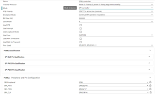
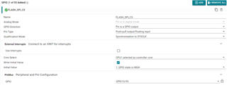
Here is how the sysconfig looks like:


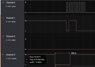
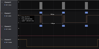
And here is what Im observing on the logic analyzer:

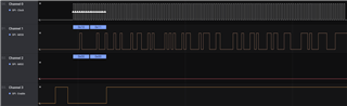
My question is what is happening with the GPIO used as SPISTE pin? Im expecting the pin to stay active low for the whole of for loop till the transmission is completed. What am I missing here?

  • Hi Harsha,

    I see that the Sysconfig data width length is 8 and the spi_transmit_multi_byte is 16 bit, why are they both different? SPI is 16-bit aligned, so you need to send 16-bits at a time.

    Best Regards,

    Aishwarya

  • Hi Aishwarya,

    Thank you for your reply. The reason I chose to use only 8bit transmission is cause Im trying to use SPI flash SST25VF020B and if you look at the command codes they are mostly 8bit long so I felt it was easier to manipulate this rather than using 16bit. I can try changing this to 16bit not sure how the flash will behave if I send 2bytes for a 1byte command code, but this does not solve the issue Im currently facing that is the manually controlled chip select pin randomly going high low while I have clearly placed clear and set gpio across the data tx function call which means that the IO should not toggle when the data is being sent on the bus but the logic analyzer clearly shows that the IO gets toggled before.

    I felt the issue could be because of the bit rate so I increased the bit rate to 25MHz but I got to this issue where the data appears on the bus after the chip select pin has been toggled already;

    So my question is when using SPI_writeDataNonBlocking function how long does it take data to be on the bus from the point the function is called.

    Next I tried using SPI_writeDataBlockingNonFIFO function but I found that it takes around 2usec to transfer 2nd byte after sending 1st, can we reduce this?

  • Harsha,

    So my question is when using SPI_writeDataNonBlocking function how long does it take data to be on the bus from the point the function is called.
    Next I tried using SPI_writeDataBlockingNonFIFO function but I found that it takes around 2usec to transfer 2nd byte after sending 1st, can we reduce this?

    Any relevant timings are provided in the datasheet here: TMS320F28003x Real-Time Microcontrollers datasheet (Rev. C). If this time is needed to be modified, you can use the GPIO as the CS and manually control it. Is there a reason you are using the GPIO as CS instead of the SPISTE pin as well? 

    Best Regards,

    Aishwarya

  • Hi,

    I figured that increasing the optimization option to 1 from off made some weird issues this being one of them, to counter I just added system delay of 1us before setting the CS to idle, thats how I was able to solve this.