This thread has been locked.

If you have a related question, please click the "Ask a related question" button in the top right corner. The newly created question will be automatically linked to this question.

TMS320F2800157: 48V Encoder motor sometimes running in uncontrolled maximum speed - Alignment issues

Other Parts Discussed in Thread: DRV8353

Tool/software:

Hello Team,

F2800157 integrated with UMC code (latest SDK_2.0.0) and gate driver specific not specific to TI tested with 48V(ABI-encoder). when try to run the motor

most the time its successful able to achieve mentioned speed and able to control the motor at mentioned speed.

With our custom board and 48V encoder, we are currently facing the following two problems.

1) Sometimes the motor runs at its uncontrolled maximum speed.

    When occasionally motor runs at uncontrollable maximum speed. It's clearly showing issues in motor alignment and encoder offset creating issues.

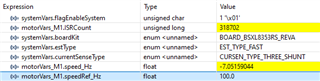
    In order to avoid offset calibration, increased Idq current at the alignment state like below. Still issues occurring rarely

   We are facing this uncontrolled speed issue in build level 4, but we are not facing this issue in build level 2 and 3.

    how to fix the alignment issues with encoder index offset calibration in build level 4?

2) Motor rated and maximum frequencies are 300 and 600 Hz respectively but in build level 4 we are not able to achieve neither rated nor maximum speed (600 Hz) using the above 48V encoder motor, when it is running        at the mentioned speed.

    But in level 2 we are able to run the motor up to its maximum frequency but only in build level 4 we are able achieve up to 260 Hz which is less than the rated speed of the motor.

    regarding this issue we have tested the motor with even less dead band but still we are not able to achieve the maximum speed.

    We are keeping the same motor parameters in builds 2 and 4, but we are still unable to reach the top speed.

    Please advise how to identify the problem so that build level 4 can operate at its fastest achievable speed.

  Thank you

 Regards,

 Kirana H P

  • As replied to you in anther thread you posted. Please check the encoder wires connection, and follow the lab guide to verify the measured angle and speed from encoder using FAST estimator. Both level 2 and 3 run the motor with open loop without using the angle and speed from the encoder.

  • Hello Yanming Luo,

    Could you please send me the encoder lab guide? It would be really helpful to me to go through it quickly.

    Regards,

    Kirana H P

  • Please take a look at the Universal Project and Lab User’s Guide: https://www.ti.com/lit/spruj26. And the detailed connection you should also refer to the motor's datasheet.

  • Hello Yanming Luo,

    Thank you for your support.

    1. I'm having trouble right now running the motor using the FAST estimator method; I'm not receiving the correct offset values.

    I have kept the circuit voltage divided like the DRV8353, but I am unable to obtain the correct voltage offset (0.6V across three phases).

    Please give me some time so that I may return with more specific information about this voltage offset and voltage divider.

    Please suggest any recommendations you may have.

    2. As mentioned in the starting of this query, 

    Motor rated and maximum frequencies are 300 and 600 Hz respectively but in build level 4 we are not able to achieve neither rated nor maximum speed (600 Hz) using the above 48V encoder motor, when it is running at the mentioned speed.

        But in level 2 and 3 we are able to run the motor up to its maximum frequency but only in build level 4 we are able achieve up to 260 Hz which is less than the rated speed of the motor.

        regarding this issue we have tested the motor with even less dead band but still we are not able to achieve the maximum speed.

        We are keeping the same motor parameters in builds 2, 3 and 4, but we are still unable to reach the top speed.

        Please advise how to identify the problem so that build level 4 can operate at its fastest achievable speed.

    Regards,

    Kirana H P

  • AS you did, you may try to run the level 1 and 2 first to verify your own board first. If the offsets are not correct, you have check the hardware circuit and ADC&PWM configuration for your own board.

    And then run the lab with level 3 to verify the current loop control, and run the lab with level 4 to identify the motor parameters. If the identified motor parameters are not correct, there may be something wrong on your own board or the parameters setting are not right.

    Make sure the hardware and software are good for running the motor first, and then check the dc bus voltage is higher enough for running the motor up to the maximum frequency.

    BTW, please take a look at the lab user's guide to monitor the related variables, and post the captured values if you still have any further questions.

  • Hello Yanming Luo,

    Thank you for your support.

    Actually, in our custom board we have maintained the voltage divider circuit same as the DRV8353 EVM board but facing the following issues.

    1. In our custom board we are not using DRV IC but instead we are using the IRF based IC. Deference between DRV IC and our custom board IC mentioned below.

    CONDITIONS DRV8353 IC CUSTOM BOARD IC
    Ideal voltage across
    voltage divider before starting the motor
    0.6V 0.3V
    Ideal voltage across
    voltage divider after starting the motor
    It will increase gradully from
     zero based on the speed_ref value
    It will increase gradully from
     zero based on the speed_ref value
    Ideal Phase voltage across
    all phases before starting the motor
    Driver IC output Same as the
     Bus voltage 
    Will get 12v across all
    the phases in ideal condition (Output from driver IC Not same as Bus voltage).

    Both the DRV and our custom board ICs function identically after turning on the motor, but only under perfect circumstances do they differ as previously stated.

    Please advise what modifications to the universal motor code are necessary to address the problem mentioned earlier.

    2. Because of above condition in our custom board, we are getting the below voltage offset values.


    Can we operate the motor at level 4 with the offset settings mentioned above?

    3. I am able to run the motor in BUILD_LEVEL2 and 3 till 160f in both the directions but not able to run the motor more than that.

        For the above activity I used the 24v motor parameters which is estimated using DRV8353 EVM with F2800157 launchpad.

    4. When I am running the motor in BUILD_LEVEL2, and 3 speed_Hz is not updating properly it is oscillating between positive and negative values as mentioned below.

    5. The motor will jerk and stop if I enable the motor debugger window, which prevents me from operating the motor in BUILD_LEVEL4.

    Would you kindly advise what needs to be considered in the universal motor code in order to operate the motor in BUILD_LEVEL4?

    Would you kindly advise us on the necessary modifications to the universal motor code to address the previously mentioned conditions?

    Regards,

    Kirana H P

  • Hello Yanming Luo,

    The DRV8353 EVM was utilised to fully understand the FAST estimator algorithm's flow.

    Please advise how to proceed with build level 4's FAST estimation approach using the IRF driver listed below.

    I've included the features of our custom board driver IC below. Since we must utilise this to run the 48v motor, kindly check once if you are concerned about our driver IC's capabilities.

    Regards,

    Kirana H P

  • As mentioned above, try to run the lab with level 2 and 3 to verify the hardware first, and then run the level 4 to identify the motor parameters. If the motor identification failed or the identified motor parameters is not correct. That means something are wrong on the hardware board or parameters setting in project,

    If possible, you can use the TI EVM to identify the motor first as a comparison.

  • Hello Yanming Luo,

    Sorry for the late reply.

    Actually, I have tested 24v encoder motor using DRV8353 EVM with F2800157 launchpad.

    If I use the above values, motor is running properly in BUILD_LEVEL_4 but if I increase these values more than 20, I have facing uncontrolled speed issue here also.

    Actually, here we are considering ABZ feedback, whenever I am increasing Acceleration values motor is running in uncontrolled speed (going to maximum speed).

    Can you please tell me why we are facing this issue when we are increasing the acceleration values.

    1. Whether index pulses are missing when we are increasing the acceleration values?


    2. How to find USER_MOTOR1_ENC_POS_OFFSET value based on the encoder sensor?

    Below I have attached the data sheet of the above 24v encoder motor.

    24V encoder motor data sheet.pdf

    Regards,

    Kirana H P

  • In our custom board also we are facing this same issue.

    In our custom board with 48v encoder motor if we maintain the speed_ref zero and if we enable run and identify flag motor going to maximum speed. For this issue any parameters we need to tune properly.

    If you have any documents related to this issue please provide me.

    Can you please suggest me, if we are going to use the different voltage divider circuit, how to adopt that to universal motor code.

    Because we are facing issue in voltage divider circuit adaptation and motor identification.

    Motor is running in build level 2 and 3 but in level 4 it is taking more current and not running.

    I am using the same 24v motor parameters which is used in drv8353 evm.

    Regards ,

    Kirana H P

  • Can you please suggest me, if we are going to use the different voltage divider circuit, how to adopt that to universal motor code.

    You should design a circuit to convert the voltage levels for C2000 EQEP with 3.3V input. Currently, we don't have any recommendation circuit for you, that could a general electrical circuit design based on your system.

    The example lab only supports ABZ encoder with 3.3V or 5V outputs on TI EVMs to EQEP to measure the speed and angle for motor control.

  • Hello Yanming Luo,

    Sorry for the late reply.

    Actually, in our current version of custom board we are using the below voltage divider circuit and here we are facing the issue with motor identification.

    Can you please suggest, for below voltage divider circuit what all are the changes we need to do in universal motor code to identify the motor properly.

    Here I am maintain the same 24v motor parameters which is used in DRV8353 EVM for identification but during inductance identification motor is stopping and Rs, rated flux and inductance values are not proper.

    In our custom board it is taking more current during identification compared to the DRV 8353 EVM identification.

    During identification, injection current is more than the mentioned value, actually current is not limiting.

    During identification voltage divider output is 200mv in DRV8353 EVM but in our custom board it is giving 600mv. Can you please suggest how to limit this value as same as DRV.

    Can you please suggest me how to analyze this problem and which parameters we need to take care here.

    Regards,

    Kirana H P

  • Seems like there is no filter capacitor (not the 1500pf) for the divided circuit. Please take a look at chapter 5.2 (Hardware Prerequisites)  and 4.1 (Currents and Voltages) of  InstaSPIN-FOC and InstaSPIN-MOTION User's Guide ( https://www.ti.com/lit/spruhj1) that have a detailed description of these.

  • Hello Yanming Luo,

    1. Actually in our custom board we are using small filter capacitor values ( 1500pf).
    2. Based on the document you have shared above now we are replacing the filter capacitor values by 47nf.

    Above approach is proper or we need to do something extra to run the motor in FAST Estimator (build level 4) with motor identification.

    Regards,

    Kirana H P

  • Sounds good. You can refer to the user's guide as mentioned above to run the motor with FAST estimator.

  • Hello Yanming Luo,

    Thank you for your support.

    Currently we are able to identify the motor using our custom board.

    But still we are facing the uncontrolled speed issue during the starting of the motor.

    Actually based on our motor encoder sensor encoder slots are 512.

    Actually I have measured the encoder A and B feedback pulses for every 360 degree mechanical rotation of the rotor using interrupt but here every time we are not getting the 512 pulses.

    Every time we are getting more than 512 pulses like 542, 534 and 572 etc.

    Actually we are tested with other two motors also but there also we are facing the same issue.

    We are unable to find the exact issue related to uncontrolled speed of the motor.

    Please suggest how to resolve this uncontrolled speed issue.

    Regards,

    Kirana H P

  • As replied to another thread you posted. Please try to run the motor with FASTfirst to verify the encoder to compare the angle and speed from FAST and encoder. The Universal can support the configuration to run the motor with FAST and encoder.

    Do you have any other motors with different encoder? Can you have a try on the other motor?

  • Hello Yanming Luo,

    Above mentioned motors are 48v encoder motors with 512 encoder slots.

    Actually I have tried with one more 24v encoder motor and I have attached the detailed data sheet of the motor below.

    Based on the motor encoder sensor it has 1000 CPR but while reading the encoder A and B signals I am getting more than 1000 pulses for every 360 degree mechanical rotation.

    Can you please mention how to resolved this issue 

    As you mentioned above can you please explain in detail that how to measure the encoder angle and how to adjust it properly.

    Regards,

    Kirana H P

  • Can you please mention how to resolved this issue 

    As mentioned above, you may try to use the FAST estimator to verify the encoder and check if the configuration for the encoder is correct. If you can make sure that the configuration are correct, but the output pulses number and the measured speed are not correct from the encoder, there is no way to resolve the issue form the software side, you should ask the manufacture of the encoder whether the encoder's specification is correct.  

  • Hello Yanming Luo,

    1. Can you please explain in detail, how to verify the encoder sensor in       FAST Estimator method because here encoder angle is               reading dynamically. Like hall sensor we are not using the fixed angles.

    2. Apart from encoder slots and EQEP related Configuration any other confirmations I need to take care?

    If you have any documents related to encoder confirmation please mention the same.

    3. Actually in DRV8353 EVM I have tested the 24v encoder (1000 encoder slots) here if I increase the acceleration_START and acceleration_MAX values in user_mtr1.h then only I am facing the uncontrolled speed issue.

    Instead if I  maintain lower values like 15 and 20 I am not facing any issues in DRV and custom board both.

    4. In our custom board I have tested the 48v encoder motor with 512 encoder slots here sometimes we are facing uncontrolled speed issue.

    At that time acceleration _START and acceleration_MAX values are 5 and 10 respectively.

    Power rating of the 48v encoder motor is 5kw so it is not possible to check with drv EVM.

    Specially we are facing this issue during the start time only. If once the motor is started properly then we are not facing this uncontrolled speed issue.

    Regarding this issue I have increased start and alignment time delays but still facing same problem.

    Can you please mention apart from this any other variables we need to tune in UMC.

    5. Motor speed is updating properly when it is running in the mentioned speed but when it is running in uncontrolled speed speed_hz is not updating properly, values are keep on changing.

    Regards,

    Kirana H P

  • You may take a look at the Universal Motor Control Lab user's guide that has the detailed description of the questions you mentioned above,

    Universal Project and Lab User’s Guide: https://www.ti.com/lit/spruj26

  • Hello Yanming Luo,

    I have followed the above document and made the related changes but still we are facing the uncontrolled speed issue during the start time of the motor.

    Let's say out of 30 times if I run the motor 1 or 2 times we are facing this issue.

    Encoder pin configuration is proper and below I have mentioned the pin configuration example, same thing only we followed for all A,B and Z feedback.

    Please suggest the way to resolve this issue.

    Apart from this I have increased start time and alignment time delays also but still facing the same issue.

    Any other tuning is required for this above issue?

    Thank you.

    Regards,

    Kirana H P

  • Any issues if you try to run the motor with sensorless FAST estimator, without using the encoder? Need to identify the issue is from the hardware board or from the encoder?

    Do you have any chance to run the other motor with the encoder? Are you using the TI's EVM boards? Or your own board?

  • Hello Yanming Luo,

    1. If I run the motor using a FAST Estimator method (in build level 2,3 and 4) even with our custom board we are not facing uncontrolled speed issue.

    2. Even if I run the motor in MOTOR1_ENC under build level 2 and 3 we are not facing this issues. As I know we are running the motor using back emf of the motor in build level 2 and 3.

    But when we are running the motor in MOTOR1_ENC under build level 4 using encoder feedback then only we are facing this issue during start time only but it is occurring occasionally.

    3. We are using DRV8353 EVM board for testing purpose like when we are facing any issues in our custom board then we will verify using DRV EVM board.

    As I know that DRV8353 gate driver IC will support motor having power rating upto 1.5kw.

    But the 48V motor we are using has a power rating of 8kW, so it is not possible to check this in DRV EVM.

    4. In our custom board also we can able to run our 48V encoder motor in both FAST and ENCODER estimator in all build levels but in encoder estimator build level 4 only we are facing this issue.

    Can I know whether we need tune any angle related parameters for above issue because we are not facing this issue in FAST Estimator.

    5. If we want to compare the FAST Estimator angle with the ENCODER estimator, then which angle-related variables do we need to compare? Because, as I know, we have many angle-related variables in the universal motor code.

    6. How to identify the issues, whether it's from hardware, encoder, or software?

    Please support us for the above activity.

    Regards,

    Kirana H P

  • But the 48V motor we are using has a power rating of 8kW, so it is not possible to check this in DRV EVM.

    4. In our custom board also we can able to run our 48V encoder m

    Perhaps in slow speed observer during open loop <1Hz the encoder interrupt priority order is causing PWM code branching making the project unstable. Can you post a scope capture of the encoder on the EQEP signal A/B output side during startup? It could even be you do not have enough bulk capacitor on VBus +48v and counter EMI/EMF is spiking the encoder signal during startup phase. Have you tried adding snubbers across the NFET phase drives?

    TI-System Design Considerations for High-Power Motor.pdf

  • Hello Genatco and Yanming Luo,

    Thank you for your support,

    1. Can you please mention, how to set the priority of the encoder interrupt and PWM code because I go through the code, and I have not found anything regarding encoder interrupt priority setting so please mention where we need to set this one.

    2. I have checked the encoder feedback; it is coming properly based on the speed and direction of the motor.

    3. When speed Ref is zero at that time if we enable the flag run and Identity it will produce 50% duty cycle across three-phases for few seconds both in DRV EVM and our custom board.

    But in our custom board sometimes when Speed ref is zero and if we enable the run and identity flag first it will produce 50% duty cycle PWM and later it is generating the PWM that should generate for higher speed, because of this motor is running at uncontrolled maximum speed.

    For zero speed ref frequency why it is generating the PWM like above?

    Please suggest the parameters need to take care for the above issue.

    4. Sometimes when we set speed ref value like 150f ,80f and 190f and then if we set the run and identity flag instead of rotating the clockwise direction it will try to move in anticlockwise direction in that particular time it will enter uncontrolled speed.

    Instead starting itself if motor try to run in mentioned direction, then it will run properly, and we will not face any uncontrolled speed issue. 

    Below I have attached the videos related to the PWM across all three phases in different circumstances, please check that suggest the way to resolve this issue.

    Thank you,

    Regards,

    Kirana H P

  • 1. When speed ref is zero and if we enable the run and identify flag sometimes it is going to uncontrolled speed below video replicate that one.

    Sometimes if we set speed ref value and then we are setting identify flag it is going to the uncontrolled speed issue.

    2. When motor is running in the mentioned speed values.

    3. Sometimes if I enable the run the identity flag when speed ref values is zero it will  generate 50% and after increasing the speed ref value also getting same PWM and it is not based on the speed we mentioned. In rare cases we are getting this issue.

    Sometimes we are getting like below also when speed ref is zero.

    Regards,

    Kirana H P

  • For zero speed ref frequency why it is generating the PWM like above?

    The 50% duty produces zero motor current is typical expected PWM behavior.

    Have you reviewed the PDF attached above post and added snubbers on half bridge NFETS? Scope VBus via single trigger capture during startup, probe AC mode millivolts check for voltage spikes?

    I have not found anything regarding encoder interrupt priority setting so please mention where we need to set this one.

    Check TRM for interrupt core priority order tables and refer to TI web page managing priority order interrupts. Perhaps ensure the encoder interrupt function asserts priority to PWM fast estimator interrupt function. You may also adjust the number of speed ticks (user.h) often causes startup issues if set to high.

    4. Sometimes when we set speed ref value like 150f ,80f and 190f and then if we set the run and identity flag instead of rotating the clockwise direction it will try to move in anticlockwise direction in that particular time it will enter uncontrolled speed.

    Run & identify mode may be getting interrupted by the encoder priory? Seemingly identify depends on FOC control, perhaps disable the encoder interrupt during motor identify. It would seem fast estimator slow speed observer <=1Hz does not play well with the encoder. Perhaps it can be disabled as mentioned. You may also reduce the trajectory acceleration (Hz/second) <10Hz, for instance try 2-5Hz. 

    More often odd behavior during startup is due to ground bounce or spikes from the motor infecting CPU code execution.

  • Hello Genatco,

    1. When speed ref is zero and if we enable run and identity flag on that time it will generate 50% duty cycle PWM, that is okay but why it is producing the PWM in a such a way that it is going to the uncontrolled maximum speed?

    Please watch the first video mentioned above for the mentioned issue.

    2. Currently we are checking the snubber circuit what we are used in our custom board is working properly or what. Can you please explain this procedure in detail.

    3. Can you please attach this TI document regarding encoder interrupt priorities. Actually I have tried to modify the ISR frequency and Ctrlperiod for the above issue is this proper approach?

    4. Currently I am maintaining the acceleration value as 5. In universal motor code it is mentioned that during the motor identification we are aligning the rotor position to zeroth position but after doing motor identification also we are facing this issue.

    5. If once the motor is running properly then we are not facing uncontrolled speed issue but if we once restart the power supply and start then sometimes it is going to maximum speed.

    6. Can you please mention in detail, how to disable this encoder interrupt during motor identification.

    7. For the above issue I have added one condition like when speed ref is zero on that time I will restart the motor control loop and If speed ref is greater than or less than zero I will enable the PWM in motor1_drive.c but in this case I have even faced the uncontrolled speed issue for single time.

    But by suddenly enabling the PWM based on speed ref value motor will jerk starting time and in dyno condition it will make loud noise because of this I have removed this condition.

    Thank you,

    Regards,

    Kirana H P

  • Hello Genatco and Yanming Luo,

    1. Actually, in our custom board we have not used the snubber circuit, and this hardware is already proved one and we are testing using universal motor code.

    2. When we set any speed ref value like 90f, 120f and 200f motor should run in the mentioned speed and direction but if it is making a small opposite rotation also, we are facing this issue and motor is going to maximum speed.

    This same situation we are facing in negative speed ref value also means instead of anticlockwise if motor makes one clockwise movement (even 5-degree rotor rotation) and then it will try to rotate in anticlockwise (mentioned direction) and suddenly it is going to uncontrolled speed.

    3. Which angle variables we need to tune, or we need to check for this issue.

    Because with HALL estimator we are not facing this issue with HALL motor in our custom board.

    Thank you,

    Regards,

    Kirana H P

  • 1. Actually, in our custom board we have not used the snubber circuit, and this hardware is already proved one and we are testing using universal motor code.

    What do you mean, statement is unclear what proved one even is. Just because Hall motor does not have issues does not mean EMI is excessive on encoder motor. Read the PDF above for clarity, typically solder a snubber cap across high side drain to low side source on each half bridge. You can never really be sure about encoder interrupt priority causing anticlockwise unless disabling the encoder interrupt test FOC mode into closed loop even stops runaway speed. 

    if motor makes one clockwise movement (even 5-degree rotor rotation) and then it will try to rotate in anticlockwise (mentioned direction) and suddenly it is going to uncontrolled speed.

    Perhaps adjust the alignment/force delta currents (user_motor1.h) for the encoder motor. If it set a bit to high odd startup behavior can be expected. Yet I would suspect the fast estimator is not always getting encoder data during the initial startup time due to interrupt priory. You could try to disable the encoder interrupt until the motor enters closed loop and stable (warmed up), >5Hz acceleration then enable the encoder interrupt.

    #define USER_MOTOR1_FORCE_DELTA_A (0.032f) // A 15% ALC (0.05f)
    #define USER_MOTOR1_ALIGN_DELTA_A (0.015f) // A 5% ALC (0.01f)  

    6. Can you please mention in detail, how to disable this encoder interrupt during motor identification.

    You have to check C code, perhaps (hal.c/h) or wherever the encoder is being configured or enable flag set enable. Search for TI Wiki C2000 ePIE interrupt nesting priority ordering to give more information on priory orders and refer to interrupt tables shown in TRM for x157 MCU.

    C28x Interrupt Nesting

  • Hello Genatco,

    Thank you for your support,

    1. I have checked the Bus voltage using oscilloscope like you mentioned above and here we are not getting any spikes while motor is running at uncontrolled speed. 

    2. Actually, in hal.h only ADC interrupt and one ePWM interrupt is confirgured.

    eQEP interrupt or encoder interrupts are not configured in hal.h in universal motor code.

    I have seen that ADC and ePWM interrupts have higher priority than eQEP interrupt, but it is not defined in hal.h.

    Please confirm once from your side.

    3. After tuning this below mentioned values, motor is not making opposite rotation but still we are facing uncontrolled speed issue.

    #define USER_MOTOR1_FORCE_DELTA_A (0.032f) // A 15% ALC (0.05f)
    #define USER_MOTOR1_ALIGN_DELTA_A (0.015f) // A 5% ALC (0.01f)  

    Thank you,

    Regards,

    Kirana H P

  • As replied to you before, it's possible to spin the motor with sensorless FAST to see if the issue is from the angle&speed measured by encoder.

    You can use a DAC or datalog with Graph to check if the angle&speed are the same from FAST and encoder. 

  • eQEP interrupt or encoder interrupts are not configured in hal.h in universal motor code.

    We have never used encoder with UMSDK though it does appear to directly support eQEP. If eQEP registers are being polled, seemingly the data is being mangled, perhaps by EMI or ground bounce infecting +5vdc. Need to add a few counter measures (hardware) get to the bottom of what is going on.

    Have you at this point added snubbers on NFET power phase drives?

    Can you post a schematic of how the custom board creates +5vdc from buck down of +48vdc? It only takes few spikes or ground bounce to cause latch-up in most all CMOS devices. Have you enabled the Watchdog timer in the project main while loop to handle a runaway code situation? Can you disable the Run_Verify flag after the runaway speed condition, reset MCU in debug or push reset button any other methods to stop the runaway speed?

    4. In our custom board also we can able to run our 48V encoder motor in both FAST and ENCODER estimator in all build levels but in encoder estimator build level 4 only we are facing this issue.

    Seemingly the motor is running open loop >1Hz build level 4 after the encoder data registers go bonkers during an uncontrolled run state. You can verify encoder data registers via CCS debug with JTAG and constant refresh register view eQEP peripheral. Being you can't test 8KW motor on launch pad, you have to use other tools and methods to sort out the issue.

  • 4. In our custom board also we can able to run our 48V encoder motor in both FAST and ENCODER estimator in all build levels but in encoder estimator build level 4 only we are facing this issue.

    Perhaps check the encoder is enabled project build level 4 properties via modify symbol (ENCODER_ENABLE) removed _N at the end.

    The encoder module is located in (encoder.h), function (static inline void ENC_run(ENC_Handle handle)).

  • Hello Genatco,

    Thank you for your support.

    1. I followed all your suggestions like adding snubber circuit and I have checked the 5v spics and ground bounce. Here we are not getting any spikes.

    2. Currently, I increased open loop frequency to 5Hz from 3Hz, so motor will enter open loop after 5Hz and I increased alignment and startup delay but there is no use.

    3. In MOTOR1_ENC under build level 4 only we are facing this issue so, as you suggested I have checked the ENC_run function for this issue.

    This function is common for all the levels and no functions are there for only build level 4.

    4. After tuning the below values, I can able to see some difference in above issue but above issue is not resolved completely.

    #define USER_MOTOR1_FORCE_DELTA_A (0.032f) // A 15% ALC (0.05f)

    #define USER_MOTOR1_ALIGN_DELTA_A (0.015f) // A 5% ALC (0.01f) 

    Can you please mention, what is the maximum values I can able to try for these variables.

    Actually these variables are not used in the UMC and it is encrypted.

    5. Any other variables we need to check or need to tune for the above issue?

    Regards,

    Kirana H P

  • Hello Yanming Luo,

    Thank you for your reply.

    1. We can able to spin our motor in FAST Estimator.

    2. In MOTOR1_ENC under build level 4 only we are facing issue.

    3. Actually, in UMC one function is there regarding phase alignment, there we are taking the FOC_angle and some default angle_rad values based on these angles we are generating new angle.

    I tried this phase adjustment or alignment functionality but I am not sure, what value we need to maintain here, in angle_rad by default there maintaining MATH_PI*0.01. Can you please tell me whether we are able to use this functionality in our code.

    If yes please mention the limit for this default angle.

    4. Can we able to run the motor in build level 3 during starting phase and switch it to build level 4 after crossing some frequency. Can we able to try this method under load condition.

    Will it make any impact on motor performance? because as I know, if we energies the stator randomly or based on the back emf it will create some issue in vehicle level.

    5. Can you please mention what percentage of current we need to maintain for alignment, startup and flux current based on the motor rated current because I have not got this information from TI document.

    6. Apart from above variables, any other variables we need to tune or check for the above issue?

    7. For the above issue I have added one condition like when speed ref is zero on that time I will restart the motor control loop and If speed ref is greater than or less than zero I will enable the PWM in motor1_drive.c but in this case I have even faced the uncontrolled speed issue for single time.

    But by suddenly enabling the PWM based on speed ref value motor will jerk starting time and in dyno condition it will make loud noise because of this I have removed this condition.

    Thank you in advance

    Regards,

    Kirana H P

  • 4. In our custom board also we can able to run our 48V encoder motor in both FAST and ENCODER estimator in all build levels but in encoder estimator build level 4 only we are facing this issue.

    Build lever 1-3 use open loop code only as Yanming mentions above.  

    It only takes few spikes or ground bounce to cause latch-up in most all CMOS devices.

    The best way you can verify very fast transition spike is present, must set scope channel AC volts, single trigger mode. Set channel trigger threshold <1 volt. 

    You can verify encoder data registers via CCS debug with JTAG and constant refresh register view eQEP peripheral.

    Have you used XDS110 debug probe JTAG to view eQEP peripheral registers during runaway speed? May only be one spike locks up the encoder, seemingly the motor never really enters closed loop current control. Perhaps try to reduce the number of speed ticks user_mtr1_h.

    //! \brief Defines the number of ISR clock ticks per speed controller clock tick
    //!
    #define USER_M1_NUM_ISR_TICKS_PER_SPEED_TICK (8) //10

    #define USER_MOTOR1_FORCE_DELTA_A (0.032f) // A 15% ALC (0.05f)

    #define USER_MOTOR1_ALIGN_DELTA_A (0.015f) // A 5% ALC (0.01f) 

    Can you please mention, what is the maximum values I can able to try for these variables.

    Actually these variables are not used in the UMC and it is encrypted.

    These values are used and Not encrypted UMCSDK, what do you mean? You confirmed changing the value helped stop random (back kick) counter clockwise rotation. 

  • Thank you for your reply Genatco,

    Yes, 1-3 build levels are open loop and it will not consider encoder feedback.

    Actually, above mentioned current values are declared in user_mtr1.h but not used in universal motor code means above variables are not used in any logic.

    Yes, after tuning above variables, random counter clockwise rotation reduced.

    Now, motor will run in mentioned direction but after few seconds suddenly it will run in counter clockwise wise direction or uncontrolled speed.

    It is happening in both the directions.

    Can I know, what is the limit for the above current variables?

    Can we able to use, PHASE_ADJUSTMENT in UMC?

    Thank you,

    Regards,

    Kirana H P

  • 2. In MOTOR1_ENC under build level 4 only we are facing issue.

    You need to check if the speed and angle are measured correctly as mentioned before. Try to use the speed and angle from FAST to verify the encoder. And it's better to use an DAC to check as shown in Universal Lab guide. 

    If possible, you can use another motor with encoder to verify the hardware and code first.

    The other parameters you mentioned above are just used for improving the startup performance, can't resolve the issue you met.

  • Hello Yanming Luo,

    Thank you for your support,

    Currently we are not facing this issue under no-load (bench) condition but in dyno(load condition) we are facing this same issue.

    In dyno, we are not giving any load during starting phase of the motor and only pulley is connected.

    Actually, for this issue I have added one condition before CL_RUNNING because when motor is entering closed loop from open loop, then only we are facing this issue.

    Here, when speed_hz is greater than 10hz, we are entering the CL_RUNNING State from OL_RUNNING and I have increased alignment delay and I maintained below values.

    #define USER_MOTOR1_FORCE_DELTA_A (0.032f) // A 15% ALC (0.05f)

    #define USER_MOTOR1_ALIGN_DELTA_A (0.015f) // A 5% ALC (0.01f).

    Currently I am not facing this issue in bench setup but during dyno only it is coming.

    In dyno sometimes it will make one rotation and suddenly it will start to rotate in opposite direction with uncontrolled speed.

    Sometimes, motor will make one rotation and it will stop.

    Apart from above current values, any other values I need to tune for this issue.

    Please mention limit for above current values.

    Regards,

    Kirana H P

  • Can you please mention, what percentage of current we need to maintain for ALIGNMENT_CURRRNT and STARTUP _CURRENT based on rated current of the motor.

    Because for Rs and Ls estimation, we have some percentage based on rated current of the motor but for above values it is not mentioned in UMCL.

    Regards,

    Kirana H P

  • Can you please mention, what percentage of current we need to maintain for ALIGNMENT_CURRRNT and STARTUP _CURRENT based on rated current of the motor

    That depends on the adding load on the motor, you need to make sure the current is enough to align the rotor to the zero position. So you can try a bit higher current, like 50% of the rated current, even much higher.

  • Hello Yanming Luo,

    Currently we are not facing this issue in load condition also; thank you for your support.

    Regards,

    Kirana H P

  • Hello Yanming Luo,

    1. Currently I am working on the regenerative braking, and I am facing some issues. In UMC, regenerative braking is not available.

    2. In universal motor code we have some brake features but among that one break feature called HARDSWITCH_BRAKE_MODE is similar to my regenerative braking algorithm.

    Here, during this brake condition we are disabling the HIGH_SIDE MOSFETs and enabling all LOW_SIDE MOSFETs.

    3. For my regenerative braking currently, I am following this below document, which was suggested by TI member.

    Wayback Machine

    In our case, when regenerative brake is applied, we need to generate the PWM to control the level of regenerative braking by varying the duty cycle of the PWM on the low side of the MOSFETs and I need to disable all HIGH-SIDE MOSFETs.

    I will use HARDSWITCH_BRAKE_MODE logic but apart from this I need to generate the PWM to control the level of regenerative braking by varying the duty cycle of the PWM on the low side of the MOSFETs.

    Can you please mention how to enable the PWM with duty cycle in UMC, because in normal motor running also, we are generating the PWM with some duty cycle based on the motor mentioned RPM.

    Thank you,


    Regards,

    Kirana H P

  • 1. Currently I am working on the regenerative braking, and I am facing some issues. In UMC, regenerative braking is not available.

    2. In universal motor code we have some brake features but among that one break feature called HARDSWITCH_BRAKE_MODE is similar to my regenerative braking algorithm.

     Only one braking mode is supported in UMC, all of the high-side are off, all of the low-side are on.

    Can you please mention how to enable the PWM with duty cycle in UMC, because in normal motor running also, we are generating the PWM with some duty cycle based on the motor mentioned RPM.

    It should be the same as spinning the motor. Please take a look at the TRM about PWM, you can configure the PWM output as you want.

  • Hello Yanming Luo,

    Thank you for your support.

    Actually, I have referred the TRM about PWM but here my requirement is during regenerative braking I need to TURN-OFF all HIGH side MOSFETs and Need to switch all LOW side MOSFETs with below mentioned duty cycle based on the RPM of the motor to increase the regenerative effect.

    But in universal motor code, I am unable to find the function or logic related to the PWM generation based on the user demanding frequency, in terms of speed Ref.

    Can you please suggest me, whether above approach is proper for regenerative braking, or you have any other algorithm for this regenerative braking?

    Currently, I am referring the below research document for implementation of the regenerative braking using PMSM motor. Is this proper approach?

    Performance_Analysis_of_Regenerative_Braking_in_Pe.pdf

    I need to switch the LOW-SIDE MOSDETs with different duty cycles based on the motor RPM, therefore if you have the source code for regenerative braking, please share it with me.

    Is it necessary to switch all LOW-SIDE MOSFETs depending on the back EMF, as shown in the diagram above?

    Since it is so important to us, could you kindly assist me with the above task?

    Thank you,

    Regards,

    Kirana H P

  • I need to switch the LOW-SIDE MOSDETs with different duty cycles based on the motor RPM, therefore if you have the source code for regenerative braking, please share it with me.

    Might try to assert DRV8353 SPI control register bool state (COAST = 1) when initial trajectory speed is set below by bool flag test into control function. Yanming mentions regen happens when rotor spins freewheeling. NFET body diodes rectify sinewave as pulsed DC back to battery. Runtime code should still monitor the bus voltage and disable regen (COAST = 0) at some over voltage point of battery recharge.  

    Scope phase voltage after motor is running and suddenly switch off DC providing Bus Voltage and MCU +3v3 power. Sometimes linear DC power supply will rectify the regeneration voltage and keep +3v3 LDO regulator active MCU powered C program running. Not sure SMP design would behave the same way. 

  • Hello Genatco and Yanming Luo,

    Thank you for your reply.

    Currently I am able to generate the PWM with some duty cycle across LOW-SIDE MOSFETs during regenerative braking condition, but the problem is, I am not able to achieve the duty cycle what I specified in the function.

    As I mentioned below, I need to turn off all the HIGH-SIDE MOSFETs and need to turn on all LOW-SIDE MOSFETs using PWM with fixed amount of duty cycle.

    Currently, in UMC PWM switching frequency is 8kHz and during regenerative brake also, I am trying to maintain the same frequency but if I maintain the same frequency I am not getting the proper duty cycle as I specified in the function.

    Every time duty cycle is changing, and I am not getting the fixed duty cycle. Here sometimes I am getting 100% duty cycle instead of 60% duty cycle.

    If I maintain less frequency like 100 or 500, I am getting PWM with 50% duty cycle but in this case also I am not getting what I mentioned in the function.

    Can you please suggest the way to resolve this issue because this is very crucial for us.

    Thank you,

    Regards,

    Kirana H P

  • Below I have attached the logic, implemented for turning on all LOW-SIDE MOSFETs during regenerative braking.

    Please check this once.

    //Regenerative braking

    static inline void HAL_enableBrakePWM(HAL_MTR_Handle handle)
    {
    HAL_MTR_Obj *obj = (HAL_MTR_Obj*) handle;
    uint16_t cnt;

    EPWM_SignalParams pwmSignal =
    { 8000, 0.4f, 0.6f, true, DEVICE_SYSCLK_FREQ,
    EPWM_COUNTER_MODE_UP_DOWN, EPWM_CLOCK_DIVIDER_1,
    EPWM_HSCLOCK_DIVIDER_1};

    Board_init();

    // // Configuring ePWM module for desired frequency and duty

    EPWM_configureSignal(MTR1_PWM_U_BASE, &pwmSignal);
    EPWM_configureSignal(MTR1_PWM_V_BASE, &pwmSignal);
    EPWM_configureSignal(MTR1_PWM_W_BASE, &pwmSignal);

    Interrupt_enable(INT_EPWM1);

    for (cnt = 0; cnt < 3; cnt++)
    {
    // setup the Action-qualifier Continuous Software Force Register (AQCSFRC)
    EPWM_setActionQualifierContSWForceAction(obj->pwmHandle[cnt],
    EPWM_AQ_OUTPUT_A,
    EPWM_AQ_SW_OUTPUT_LOW);
    // setup the Dead-Band Generator Control Register (DBCTL)
    EPWM_setDeadBandDelayMode(obj->pwmHandle[cnt], EPWM_DB_RED, false);
    EPWM_setDeadBandDelayMode(obj->pwmHandle[cnt], EPWM_DB_FED, false);
    }
    #endif

    obj->flagEnablePWM = true; //false

    return;
    } // end of HAL_enableBrakePWM() function

    Regards,

    Kirana H P