Part Number: TMS320F28377D
Other Parts Discussed in Thread: TIDA-01606
Tool/software:
Having problems achieving the PLL operation.
I;m mainly looking into the TIDA-01606 for inverter operation.
My goal is to run inverter operation that is connected to the grid. (380Vrms line to line, 60Hz)
 // Read ADC results
    VA = ADC_readResult(ADCBRESULT_BASE, ADC_SOC_NUMBER0);
    VB = ADC_readResult(ADCBRESULT_BASE, ADC_SOC_NUMBER1);
    VC = ADC_readResult(ADCBRESULT_BASE, ADC_SOC_NUMBER2);

    // DATA should be centered at 0 while having peak of 1 or -1.
    // SInce the ABC to DQ0 transformation is going to happen. sine-wave
    VA_pu = ((float32_t)VA - Vgrid_Sense_Offset_A) / Vgrid_Sense_peak2peak_A;  // 변수 변경 가능
    VB_pu = ((float32_t)VB - Vgrid_Sense_Offset_B) / Vgrid_Sense_peak2peak_B;
    VC_pu = ((float32_t)VC - Vgrid_Sense_Offset_C) / Vgrid_Sense_peak2peak_C;
using the above code and the ADCSOC.
void initADCSOC(void)
{
    uint16_t acqps = 14; // Acquisition window size

    // Configure SOCs to be triggered by CPU Timer 0 interrupt
    ADC_setupSOC(ADCB_BASE, ADC_SOC_NUMBER0, ADC_TRIGGER_EPWM1_SOCA,
                 ADC_CH_ADCIN0, acqps);    // Pin B0
    ADC_setupSOC(ADCB_BASE, ADC_SOC_NUMBER1, ADC_TRIGGER_EPWM1_SOCA,
                 ADC_CH_ADCIN14, acqps);   // Pin B14
    ADC_setupSOC(ADCB_BASE, ADC_SOC_NUMBER2, ADC_TRIGGER_EPWM1_SOCA,
                 ADC_CH_ADCIN15, acqps);   // Pin B15

    // Configure interrupt to occur after SOC2 conversion
    ADC_setInterruptSource(ADCB_BASE, ADC_INT_NUMBER1, ADC_SOC_NUMBER2);
    ADC_enableInterrupt(ADCB_BASE, ADC_INT_NUMBER1);
    ADC_clearInterruptStatus(ADCB_BASE, ADC_INT_NUMBER1);
}
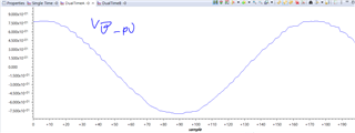
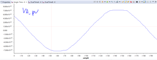
the sensed values are quite similiar to the sine-wave. like below.
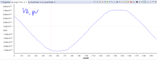
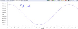
similar to the LAB1-4 of the TIDA-01606,
the sensed values are transformed to DQ0 form using the ABC to DQ0 POS.h (from the ti's library) function.
    // Perform ABC to DQ0 transformation
    ABC_DQ0_POS_run(&Vgrid_abc2dq0_pos,
                    VA_pu, VB_pu, VC_pu,
                    sine_VAL, cosine_VAL);
and run SPLL using spll_3ph_srf.h
    // Run the SPLL algorithm
    SPLL_3PH_SRF_run(Vgrid_abc2dq0_pos.q, &grid_SPLL);

    // Update the angle from SPLL
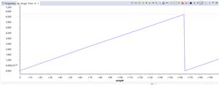
    angleSPLL_radians = grid_SPLL.theta[0];
    sine_VAL = sinf(angleSPLL_radians);
    cosine_VAL = cosf(angleSPLL_radians);
finally, run dq0 to abc to generate a duty ratio for phase A, B, C.
 // Perform DQ0 to ABC transformation to get inverter voltage references
    DQ0_ABC_run(&Vgrid_dq02abc,
                Vd_pu, Vq_pu, Vz_pu,
                sine_VAL, cosine_VAL);

    //DQ0 to ABC
    duty_A = (Vgrid_dq02abc.a * 0.5f) + 0.5f;
    duty_B = (Vgrid_dq02abc.b * 0.5f) + 0.5f;
    duty_C = (Vgrid_dq02abc.c * 0.5f) + 0.5f;

    // 12. Clip duty cycles to [0, 1]
    duty_A = fminf(fmaxf(duty_A, 0.1f), 0.9f);
    duty_B = fminf(fmaxf(duty_B, 0.1f), 0.9f);
    duty_C = fminf(fmaxf(duty_C, 0.1f), 0.9f);

    //sine values to DUTY
    uint16_t cmpValueA = (uint16_t)(EPWM_TIMER_TBPRD * duty_A);
    uint16_t cmpValueB = (uint16_t)(EPWM_TIMER_TBPRD * duty_B);
    uint16_t cmpValueC = (uint16_t)(EPWM_TIMER_TBPRD * duty_C);
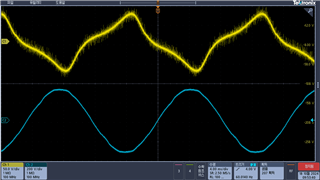
well, I think the PLL operation and the flow is right but, the result of this didn't generate the sine-wave. rather it produced a distorted wave.
I setted the coefficients same as the example part
 // Adjust coeffiecients. TI's library follow.
    grid_SPLL.lpf_coeff.b0 = 333.807f;
    grid_SPLL.lpf_coeff.b1 = -333.674f;
and also with the d.q.z values.
//DQ0 to ABC
const float32_t Vd_pu = 0.835f;
const float32_t Vq_pu = 0.0f;
const float32_t Vz_pu = 0.0f;
is there any advice to achieve the pll operation with the grid-tied inverter?
THANKS.