Tool/software:
Hey,
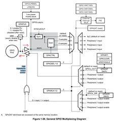
I am noticing something strange with specific GPIOs that are configured as outputs. The code below is how GPIO30 and GPIO25 are configured. While my project is running, in a scenario with a lot of switching noise, these GPIOs tend to “toggle” themselves without me writing any command to do so.
GpioCtrlRegs.GPAMUX2.bit.GPIO30 = 0; // GPIO30 = GPIO30
GpioCtrlRegs.GPADIR.bit.GPIO30 = 1; // GPIO30 = OUTPUT
GpioCtrlRegs.GPAPUD.bit.GPIO30 = 0; // Disable pullup on GPIO30
GpioCtrlRegs.GPAMUX2.bit.GPIO25 = 0; // GPIO25 = GPIO25
GpioCtrlRegs.GPADIR.bit.GPIO25 = 1; // GPIO25 = OUTPUT
GpioCtrlRegs.GPAPUD.bit.GPIO25 = 0; // Disable pullup on GPIO25
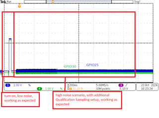
These GPIO outputs are some of few that are routed right under some High Voltage switching, it will pick up a lot of noise in certain scenarios. When the project is in a low noise scenario, the GPIO behaves fine, only doing exactly what it is programmed to do. But when it is in a high noise scenario sometimes randomly this GPIO will toggle on its own. While monitoring the GpioDataRegs.GPADAT.bit.GPIO30 bit during debug, it will change from 0->1 or 1->0 on its own. I have removed all set/clear/dat commands to just observe the behavior all on its own. Below is a screenshot of GPIO30 and GPIO25 behaving this way (they both are routed near the HV switching noise source).

So my question is why is this happening? If my GPIO is set as an output, it shouldn’t toggle/latch/change states without my code telling it to. Does high noise have a change to influence this GPIO to change states?
Our current work around right now is to assume this GPIO is constantly being read by the micro, as if it were an input, and maybe tricking itself when it reads noise and toggles itself. So, the below code is additional Qualification Window GPIO setup, assuming as if it were an input. Below the code is a screenshot of GPIO30 and GPIO25 with this extra setup.
GpioCtrlRegs.GPACTRL.bit.QUALPRD3 = 0x4B; //(75x2)/(90Mhz)=period
GpioCtrlRegs.GPAQSEL2.bit.GPIO30 = 2; //6 sampling window
GpioCtrlRegs.GPAQSEL2.bit.GPIO25 = 2; //6 sampling window
Thanks for any help or insight, it is appreciated