This thread has been locked.

If you have a related question, please click the "Ask a related question" button in the top right corner. The newly created question will be automatically linked to this question.

TMS320F28388D: Clocking an SPI Peripheral via CLB

Part Number: TMS320F28388D


Tool/software:

Hello,

I am working on setting up an SPI peripheral with the SPI clock (SPI-CLK) sourced from a clock generated by the CLB.

To test this configuration, I attempted to use the SPI loopback mode. The SPI setup is shown in the attached configuration image.

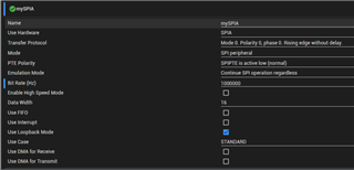
Here are the details of my setup:

  • I have generated the clock (1MHz) via the CLB and connected this signal to the SPI CLK pin through GPIOs.
  • The SPI PTE pin is connected to ground, also via GPIOs.
  • I am monitoring all of these signals using an oscilloscope.

When the SPI is in Controller/Master mode, with the CLB clock disconnected from the SPI CLK pin, the loopback works correctly.

However, when I switch the SPI to Peripheral mode and connect the CLB clock to the SPI CLK pin, the SPI POCI pin (MISO) remains high. I have verified the contents of the SPI TXBUF and SPIDAT registers. While SPI TXBUF shows the expected value, SPIDAT consistently reads 0xFFFF.

Any insights into what might be causing this issue would be greatly appreciated.

Is it possible to use loopback mode with SPI in Peripheral mode?

Thank you!

Regards,

Wilko

  • Hi Wilko,

    Apologies for the delay, I was out of office. It looks like the clock generated from the CLB is working and that a jumper is used to connect the CLB CLK to the input of the SPI. For SPI internal loopback mode, the SPI connects the PICO and POCI internally and disregards what is happening on the GPIO. If you want to use GPIO connections, you'll need to disable SPI loopback mode.

    Best Regards,

    Aishwarya

  • Hello Aishwarya,

    Thank you for your response.

    I have made some progress with the issue but have not completely resolved it. The CLB output is internally connected to the SPI clock. I disabled the loopback mode, but this did not solve the problem.

    Next, I experimented with the SPI clock, extending its active duration. This approach yielded some useful insights: I discovered that the SPI starts transmitting data only after a sufficient number of clock cycles have elapsed. Specifically, in my case, the SPI requires 13 clock cycles before the SPI peripheral starts sending data.

    Given this behavior, my follow-up question is: what could be causing such a significant delay, and are there ways to reduce this delay?

    Regards,

    Wilko

  • Hi Wilko,

    Thanks for providing this additional information. Are you always seeing 13 clock cycles? SPI does have a setup time requirement which is the minimum time before the SPI can start a transmission, but it is not this long. Can you verify your SPI configurations again? Is it still the same ones in the screenshot. You can refer to the datasheet on the specifics of these timing requirements.

    Best Regards,

    Aishwarya

  • Hi Aishwarya,

    Yes, there are always 13 clock cycles, and the SPI configuration remains the same as shown in the screenshot.

    I suspect there may be an issue with my clocking or perhaps a synchronization problem with the clock.

    Regards,

    Wilko

  • Wilko,

    Apologies for the delay due to the U.S. Holidays. It looks like the CLB CLK is potentially not synchronized with the SPI module. Verify the following items, and let me know if you have any questions.

    1. Use an oscilloscope to verify the CLB generated SPI CLK has the proper timing, specifically that it aligns with data sampling requirements related to user configured polarity, phase, frequency, etc. when it is sent to the SPI CLK pin. This clock needs to follow the datasheet timing requirements for setup, rise, etc. times.
      1. This is important because the SPI module and CLB clock need to be synchronized, so that the SPI can correctly sample transmitted data and then read it.
    2. Ensure the GPIO used for SPICLK is configured as an input in peripheral mode. On the CLB side, make sure the clock is being routed to this GPIO properly.
    3. Verify that user configured polarity, phase, frequency, etc. are consistent across SPI and CLB. If you haven't already, I'd disable loopback mode because this mode typically assumes the SPI is in controller mode.

    If the above do not help solve the issue, there could be an issue with the CLB configuration and the clock generation there. I will also loop in our CLB expert here regarding the CLB configurations, if you're able to provide those related details

    Best Regards,

    Aishwarya