This thread has been locked.

If you have a related question, please click the "Ask a related question" button in the top right corner. The newly created question will be automatically linked to this question.

TIDM-DC-DC-BUCK: C2000 microcontrollers forum

Part Number: TIDM-DC-DC-BUCK
Other Parts Discussed in Thread: BOOSTXL-BUCKCONV, SYSCONFIG

Tool/software:

Hi.

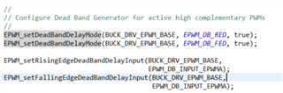
I am learning how to program the C2000 to control the eval board BOOSTXL-BUCKCONV. I was studying the code of the buck-F28004x and I found a part that it is difficult to understand. So in the function

 BUCK_HAL_setupSyncBuckPwm();

there is an function that it is called

EPWM_setCounterCompareShadowLoadMode(BUCK_DRV_EPWM_BASE,
EPWM_COUNTER_COMPARE_A,
EPWM_COMP_LOAD_ON_CNTR_PERIOD);

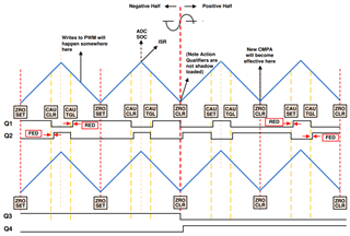
I understand what it does, but my question is: how do I determine whether to use LOADAMODE = 0, 1, or 2? My understanding is that the COMPA register will be updated either at the beginning of the duty cycle or after TBCTR = TBPRD, with the counter being updated in the next cycle.

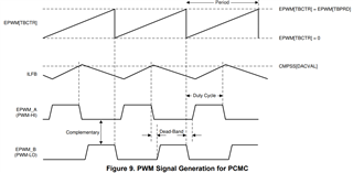
For voltage mode control, the code uses 0x01. Why not 0x00, for example? If I choose peak current mode control, should I use 0x00 because the counter needs to be updated immediately?

  • Hi Andres,

    Choosing the LoadMode is a consideration of a combination of different factors, including control mode, ISR trigger, and control period. 

    For this project, resetting at TBPRD and at ZERO are virtually identical since the PWM is configured in up-count mode, whenever the TBCTR reaches the TBPRD, it will reset back down to zero. 

    For peak current mode control, we are not using the PWM compare module to control the duty of the PWM. Instead, the CMPSS module is used to compare the ILFB to some internal DAC value which is configured in the code (static in open-loop, variable in closed-loop), so then the Load Mode doesn't make a difference

    Regards,

    Peter

  • Ok, I see. So most of the applications that use Voltage mode control doesn't affect if it is LOADAMODE  = 0 or 1. Could you give an example (if it is possible) when the LOAD Mode is important? Because I do not see why there is an option between  TBCTR = TBPRD or  TBCTR = 0 if in the end, the COMPA will behave exactly the same

  • Hi Andres,

    The Load Mode has an impact when the PWM counter is configured in up-down-count mode. In this mode, the PWM counter will increment to the TBPRD. Afterwards, it will decrement to zero. In these instances, you may want to alter the load mode depending on at what point in the PWM cycle you want to ensure consistent operation across cycles. See below diagram illustrating such

    Regards,

    Peter

  • Hi Peter. 

    I am reading the Deadband section and have two questions. If they wanted to enable Active High Complementary (AHC) PWM, which requires DBCTL->OUT_MODE = 0x11, why did they call the function twice instead of passing the value 0x11 directly?

    For the Falling Edge Band Delay Input, they set DBCTL->DEB_MODE = 0. According to the description, this means the rising-edge delay will only apply to the A signal path, and the falling-edge delay will apply to the B signal path. However, if I have AHC, both the rising and falling edges (A and B signals) should have delays, right? Otherwise, if only B has a delay on the falling edge and A has a delay on the rising edge, there will be issues with A's falling edge and B's rising edge, as neither will have a delay.

  • HI Andres,

    why did they call the function twice instead of passing the value 0x11 directly

    You can pass 11 directly if you are writing to the registers directly, but given the way the DriverLib library is structured, the code requires setting each bit individually. If you are using SysConfig, the active high complementary shortcut will automatically configure the DB registers for you.

    ccording to the description, this means the rising-edge delay will only apply to the A signal path, and the falling-edge delay will apply to the B signal path. However, if I have AHC, both the rising and falling edges (A and B signals) should have delays, right?

    In AHC mode, the A leg is replicated to the the B leg and inverted. So in this case, they have configured both rising and falling edges to affect the A leg so that they can control both sides. Since B is unused, there is no need to configure the FED or RED for B side

    Regards,

    Peter