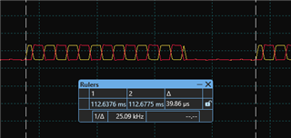
I am working with two PWM signals: PWM1 with a frequency of 25 kHz, Duty 80% and PWM2 with a frequency of 250 kHz duty 50%(which can be adjusted at runtime).
Here is the current approach I am using:
- I generate an interrupt from PWM1 on a CMPX event during both up-counting and down-counting phases. The interrupt source is toggled within the ISR, so the first time the interrupt is triggered on the up-count, and the second time it is triggered on the down-count CMPX event.
- When the PWM1 counter is counting up and the ISR is executed, a flag is set to 1. During the down-count CMPX interrupt, the flag is set to 0.
- I generate an interrupt from PWM2(250Khz) at every CMPX event during the up-count phase.
- In the PWM2 ISR, I read the flag set by PWM1. If the flag is 1, PWM2 (250 kHz) is enabled using the TZ module. If the flag is 0, PWM2 is turned off using the TZ module.
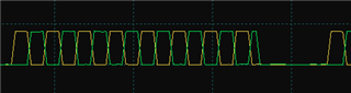
Observation:
- The PWM signal is on at the start and off at the end, but this does not maintain a symmetric PWM pattern.
Issue:
- How can I achieve symmetric PWM switching, ensuring the PWM turns on and off in a symmetric manner? Please suggest methods to achieve symmetric PWM.