Tool/software:
Hi everyone,
I've been trying for days to debug my f28p65x Launchpad through an external debugger LP-XDS110 (I'm doing since i wanted to test the debug probe with a simple pcb as the Launchpad before using for another project).
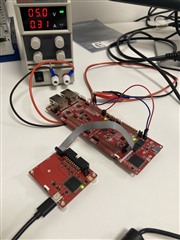
I removed the two jumpers which bring power from usb to mcu and I supplied the Launcpad through a dc power supplier with 5v (in order to use an external debugger).
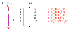
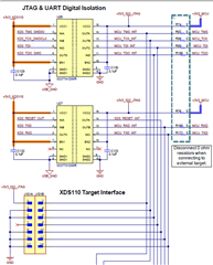
Then I connected TMS, TCK, TDO, TDI, VREF, GND and XRS to the 14-pin connector placed on the F28P65x. I'm attaching a photograph of the rough setup.

When i try to test the connection in the target configuration file, I get the following script:
[Start: Texas Instruments XDS100v3 USB Debug Probe_0]
Execute the command:
%ccs_base%/common/uscif/dbgjtag -f %boarddatafile% -rv -o -F inform,logfile=yes -S pathlength -S integrity
[Result]
-----[Print the board config pathname(s)]------------------------------------
C:\Users\EliaMura\AppData\Local\TEXASI~1\
CCS\ccs1260\0\0\BrdDat\testBoard.dat
-----[Print the reset-command software log-file]-----------------------------
This utility has selected a 100/110/510 class product.
This utility will load the adapter 'jioserdesusbv3.dll'.
The library build date was 'Sep 26 2024'.
The library build time was '10:09:41'.
The library package version is '20.0.0.3178'.
The library component version is '35.35.0.0'.
The controller does not use a programmable FPGA.
The controller has a version number of '4' (0x00000004).
The controller has an insertion length of '0' (0x00000000).
This utility will attempt to reset the controller.
This utility has successfully reset the controller.
-----[Print the reset-command hardware log-file]-----------------------------
The scan-path will be reset by toggling the JTAG TRST signal.
The controller is the FTDI FT2232 with USB interface.
The link from controller to target is direct (without cable).
The software is configured for FTDI FT2232 features.
The controller cannot monitor the value on the EMU[0] pin.
The controller cannot monitor the value on the EMU[1] pin.
The controller cannot control the timing on output pins.
The controller cannot control the timing on input pins.
The scan-path link-delay has been set to exactly '0' (0x0000).
An error occurred while hard opening the controller.
-----[An error has occurred and this utility has aborted]--------------------
This error is generated by TI's USCIF driver or utilities.
The value is '-501' (0xfffffe0b).
The title is 'SC_ERR_TEST_MEASURE'.
The explanation is:
The built-in scan-path length measurement failed.
The built-in scan-path reliability tests cannot be
performed without knowledge of the scan-path length.
Try specifying the scan-path lengths in the command-line
options or board configuration file of this utility or debugger.
[End: Texas Instruments XDS100v3 USB Debug Probe_0]
I've been searching for solutions here on the forum but without any luck.
Could you please give me any suggestion?


