This thread has been locked.

If you have a related question, please click the "Ask a related question" button in the top right corner. The newly created question will be automatically linked to this question.

TMDSCNCD28P65X: SCIFLR overrun bit error set

Part Number: TMDSCNCD28P65X


Tool/software:

Hi all,

We are testing the LIN reception phase of a LIN Responder (Slave) node using a Vector CANalyzer with a LIN IG (simulated Master) for sending messages both manually and periodically (project needing should be 100msec scheduling).

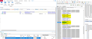
At each message reception, we are monitoring the SCIFLR register values for error/status analysis.

Sometimes but not always, the overrun OE flag is set by the peripheral and I do not have understood the reason.

All the other error flags (PE, CE, etc) are 0, as expected.

Consider that:

  1. 19.2 kbps is the baudrate,
  2. Autobaudrate detection is disabled,
  3. LIN commands (header+response) are sent manually and not periodically, with the LIN IG.

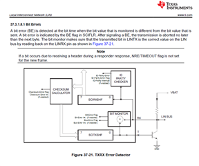
According to "Table 37-22. SCIFLR Register Field Descriptions" of spruiz1a – JULY 2023 – REVISED NOVEMBER 2023

So, what does it mean? Are there unread bytes of RDy buffers when a new message is received?

B.R.

Andrea

  • Hi Andrea,

    I apologize for my delayed response.

    Are there unread bytes of RDy buffers when a new message is received?

    Yes, the OE flag effectively means that received data has been lost since new data came in and overwrote it before it was read from RDy. A couple things to look into:

    Are you using a LIN RX ISR? Does this ISR take particularly long to execute?

    Do you have other interrupts enabled in the application? Its possible higher priority interrupts could be blocking the LIN interrupt from executing.

    Do you have multi-buffer enabled? If not, I would suggest enabling it, so you have more space to store incoming data before it needs to be read.

    I would also suggest setting up the interrupt for this flag so that you can properly clear it each time it's raised. That way you can accurately see how often this condition is happening.

    Best Regards,

    Delaney

  • Hi Delaney,

     I try to answer to your 

    Are you using a LIN RX ISR? Does this ISR take particularly long to execute?

    No, we are not using ISR neither DMA, only peripheral register polling; we know that ISR, DMA and their cross usage could help us (as usual for communication peripherals) but for project and architecture reason, they cannot be used (application runs with a simple monotonic counter, RTOS or similar are not used)

    Do you have other interrupts enabled in the application? Its possible higher priority interrupts could be blocking the LIN interrupt from executing

    I have to investigate with my collegues about the C2000 PIE configuration 

    I would also suggest setting up the interrupt for this flag so that you can properly clear it each time it's raised. That way you can accurately see how often this condition is happening.

    I would like but I cannot do it for the reason listed above.

    Best Regards,

    Andrea

  • Hi Delaney,

     Testing the Response Tx (our device is a Responder/Slave), we have noticed that after a successful transmission, transmitted data are copied into the LIN RDy register.

    In the first moment that behavior was not explicable from our side, but maybe the explanation is already contained in the C2000 RM.

    If we look at the Bit Error detection block depicted below

    "The bit monitor makes sure that the transmitted bit in LINTX is the correct value on the LIN bus by reading back on the LINRX".

    That statement explains the copy of TDy transmission data register into RDy reception data register and next RXRDY setting.

    In this way, Overrun Errors are easily triggered when full comands (header+response from master) and three more header only are added to the simulation

    We have added a workaround at the end of transmission phase

            /* Transmission completed */
            /* Check of transmission errors*/
            retLinSts = LIN_GetStatus(LIN_CHANNEL_USED);
    		if ((retLinSts & LIN_TX_BIT_ERROR) == LIN_TX_BIT_ERROR)
    		{
    		   retTxStatus = COM_LIN_TX_BIT_ERR;
    	    }
    		else if ((retLinSts & LIN_TX_ERROR) == LIN_TX_ERROR)
    		{
       		   retTxStatus = COM_LIN_TX_ERR_STATUS;
            }	
    		else
    	    {	
      		   retTxStatus = COM_LIN_TX_COMPLETED;
    		   /* Workaround to clear the Rx ready flag set by Tx bytes that are also routed to Rx data registers */
    		   if (LIN_isRxReady(LIN_CHANNEL_USED) == TRUE)
    		   {
    				LIN_ClearRxReady(LIN_CHANNEL_USED);
    		   }
    	    }

    in this way, none OE flag is triggered, neither with the full LIN scheduler on going, all receptions and transmission are completed successully.

    Just for confirmation, is it correct our interpretation? Is this behavior related (and expected by the way) to the LIN module strategy of bit error checking described in the RM?

    Best Regards

    Andrea

  • Hi Andrea,

    I apologize for my delayed response. Yes, you bring up a good point. The data transmitted by the LINTX pin will be looped back around (internally) and received on the LINRX pin for the bit error checker. In this case, the OE flag can be ignored since it isn't a valid error anyways (since you don't care about reading this data in - it is being transmitted out in your application). However, if you want to avoid the flag from being raised altogether, you can clear the RX ready flag in software as you are doing.

    Best Regards,

    Delaney

  • Hi ,

     Do not worry about,

    As you can see, I am answering almost one month later Slight smile.

    So our workaround is working as expected.

    Very very good.

    Thanks a lot.

    K.R.

    Andrea 

  • Hi Andrea,

    Glad to hear the issue is resolved, I will close this thread but please feel free to make a new one if you have any more questions.

    Best Regards,

    Delaney