Other Parts Discussed in Thread: MSPM0G3507
Tool/software:
Hello my dear supporters and engineers,
I am trying to implement LIN communication using MSPM03507.
So, I tried to use the example code in the "C:\ti\mspm0_sdk_2_02_00_05\examples\nortos\LP_MSPM0G3507\lin\lin_responder" path, but it is far from the purpose of my design, so I would like to ask for another example.
I will share with you the problems that arose while implementing LIN communication.
Problem 1.
The RX data I want to transfer from the controller to the slave board has the following format:
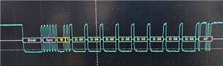
Therefore, I plan to use the 9 Bit Address Mode method.
The initialization settings have been changed as follows:
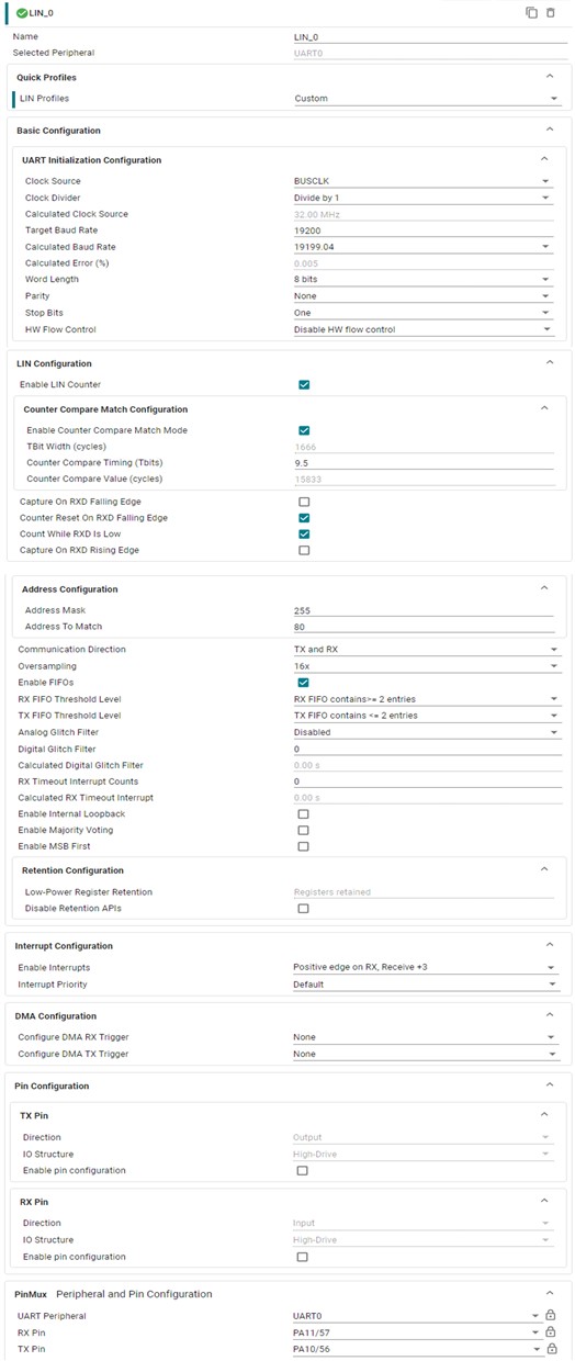
However, it is also necessary to configure parts that are not already set in SYSCOFIG.
Looking at the register status,
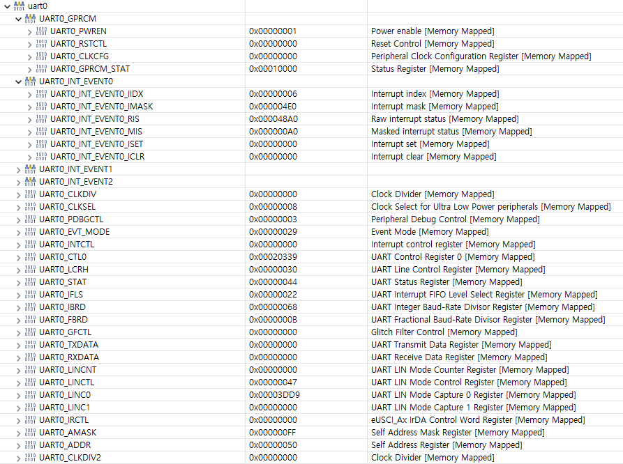
In my opinion, bit 0 of the LCRH register should be set to 1, and bit 0 of the INTCTL register should be set to 1.
Alternatively, you can consider setting bits 1 and 0 of the EVT_MODE register to 1 to modify the interrupt clear method to a hardware method rather than a software method. (However, I did not try it because I do not have information about the hardware automatic clear conditions.)
Problem 2.
When performing LIN communication using the example code in "C:\ti\mspm0_sdk_2_02_00_05\examples\nortos\LP_MSPM0G3507\lin\lin_responder", the LIN_0_INST_IRQHandler interrupt does not occur.
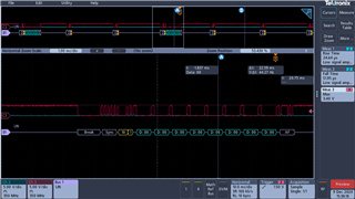
When LIN communication is performed with a break in the first sentence of LIN_0_INST_IRQHandler in debug mode, an interrupt must be generated under the RXINT, LINC0, RXPE, and RXNE conditions set as the interrupt mask, but the break does not occur even if an RX signal like the picture at the top is sent.
However, if you directly set the bits to 1 in the UART0_INT_EVENT0_ISET register through debug mode, a break is entered in the interrupt statement.
Therefore, I suspect that the interrupt-related flag does not seem to be set to 1 even though it is an interrupt occurrence condition.
I look forward to a quick response to these issues.
If you need any further information - feel free to ask!
Donguk