This thread has been locked.

If you have a related question, please click the "Ask a related question" button in the top right corner. The newly created question will be automatically linked to this question.

TMS320F28379D: ADC configuration for sensor reading

Part Number: TMS320F28379D


Tool/software:

Hello all,

I'm using a Delfino F2837xD controlCard in a power converter application and I'm trying to acquire the DC voltage applied to the power converter.

The CPU clock is set to 200 MHz, while the ADC clock is 50 MHz. I'm working on Simulink environment using the C2000 Microcontroller Blockset add-on to communicate with HW.

The ADC block configuration is the following:


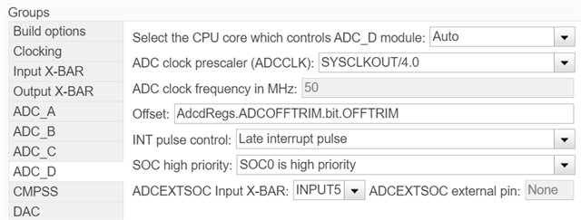
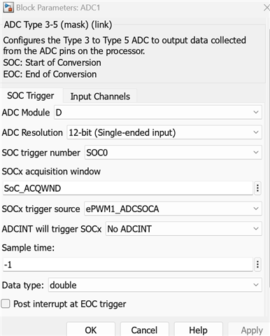
As you can see the ADC start of conversion (SOC0) is triggered by an ePWM module at a frequency of 20kHz.

The acquisition window is the point of this discussion. I read from the documentation that the sampling acquisition time should me at least equal to the period of the ADC cycle (which is 20ns), in our case it results in a minimum acquisition window of 3. But using this value I read a voltage value with a very huge offset with respect to the operating voltage (given to the system through a DC voltage power supply). For this reason the sampling window value is set to 6, which gives the minimum offset with respect to the operating voltage.

Can anyone explain me the reason about this point?

Also, the voltage values is very noisy, as you can see from the acquisition below:

While the temperature value is better in terms of variance, with the same configuration. Is there any reason about the poor quality of the signal? I read about PPBs blocks, which should post-process the raw input signal. Are these blocks already active "by default" or should I configure them to use the feature? 

Thank you a lot. 

Regards,

Lorenzo

  • Hi,

    I will need a few days to get back to you.

    Best Regards,

    Ben Collier

  • Are these blocks already active "by default" or should I configure them to use the feature? 

    Hi Lorenzo,

    You have to configure PPB's in (hal.h) if using TI example projects or even your own code to use and read the PPB's sample data. Below example from universal motor control SDK.

    // x49c MCU class
    
    #define MTR1_IU_ADC_SOC_NUM     ADC_SOC_NUMBER1         // ADCA-A4*/B8  -SOC1-PPB2
    #define MTR1_IV_ADC_SOC_NUM     ADC_SOC_NUMBER8         // ADCA-A8*     -SOC8-PPB3
    #define MTR1_IW_ADC_SOC_NUM     ADC_SOC_NUMBER9         // ADCB-B4*/C8  -SOC9-PPB4
    
    
    #define MTR1_IU_ADC_PPB_NUM     ADC_PPB_NUMBER2         // ADCA-A4*/B8  -SOC1-PPB2
    #define MTR1_IV_ADC_PPB_NUM     ADC_PPB_NUMBER3         // ADCA-A8*     -SOC8-PPB3
    #define MTR1_IW_ADC_PPB_NUM     ADC_PPB_NUMBER4         // ADCB-B4*/C8  -SOC9-PPB4
    
        // !(MOTOR1_DCLINKSS)
    #if defined(LPD_SITE_J5_J8) && defined(_F28004x) && defined(BSXL8320RS_REVA)
        // convert phase A current          ADCA-A4*/B8->RB0    
        value = (float32_t)ADC_readPPBResult(MTR1_IU_ADCRES_BASE, MTR1_IU_ADC_PPB_NUM);
        pADCData->I_A.value[0] = value * pADCData->current_sf;
    
        // convert phase B current          ADCA-A8*->RA0      
        value = (float32_t)ADC_readPPBResult(MTR1_IV_ADCRES_BASE, MTR1_IV_ADC_PPB_NUM);
        pADCData->I_A.value[1] = value * pADCData->current_sf; //
    
        // convert phase C current          ADCB-B4*/C8->RC0    
        value = (float32_t)ADC_readPPBResult(MTR1_IW_ADCRES_BASE, MTR1_IW_ADC_PPB_NUM);
        pADCData->I_A.value[2] = value * pADCData->current_sf;
        
        //hal.c setup PPB's
        
        // Configure PPB2 to eliminate subtraction related calculation
        // PPB is associated with ADCA_SOC1
        ADC_setupPPB(MTR1_IU_ADC_BASE, MTR1_IU_ADC_PPB_NUM, MTR1_IU_ADC_SOC_NUM);
    
        // Write zero to this for now till offset calibration complete PPB2
        ADC_setPPBCalibrationOffset(MTR1_IU_ADC_BASE, MTR1_IU_ADC_PPB_NUM, 0);
        
        // Configure PPB3 to eliminate subtraction related calculation
        // PPB is associated with ADCB_SOC8
        ADC_setupPPB(MTR1_IV_ADC_BASE, MTR1_IV_ADC_PPB_NUM, MTR1_IV_ADC_SOC_NUM);
    
        // Write zero to this for now till offset calibration complete PPB3
        ADC_setPPBCalibrationOffset(MTR1_IV_ADC_BASE, MTR1_IV_ADC_PPB_NUM, 0);
        
        // Configure PPB4 to eliminate subtraction related calculation
        // PPB is associated with ADCA_SOC9
        ADC_setupPPB(MTR1_IW_ADC_BASE, MTR1_IW_ADC_PPB_NUM, MTR1_IW_ADC_SOC_NUM);
    
        // Write zero to this for now till offset calibration complete PPB4
        ADC_setPPBCalibrationOffset(MTR1_IW_ADC_BASE, MTR1_IW_ADC_PPB_NUM, 0);