Other Parts Discussed in Thread: TMS320F28335, TMS320F28379D, C2000WARE
Tool/software:
Issue Description: eQEP Frequency Calculation Anomaly on DSP TMS320F28379D
I am currently using the LAUNCHXL-F28379D development board, connected to a three-phase inverter controlling a motor. The system setup is as follows:
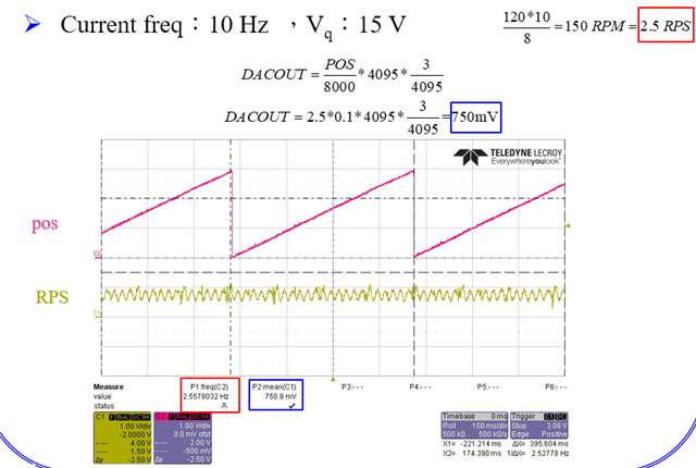
- Current frequency: 10 Hz
- ADC interrupt frequency: 10 kHz
- Motor specification: 8 poles, expected speed of 150 RPM (verified with a tachometer)
- Encoder resolution: 10000 CPR, using only A/B phase inputs without the Index signal
- eQEP initialization: Based on the official example
Eqep_pos_speed.c - When manually rotating the motor for one complete revolution, the oscilloscope shows a correct and complete waveform, confirming that the encoder signals are not faulty
Problem:
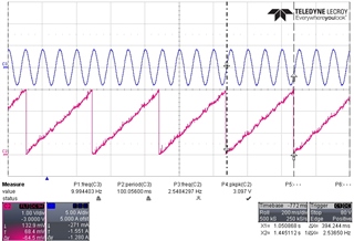
- When outputting the QPOSCNT value as an analog signal via DAC, the expected frequency is 2.5 Hz (corresponding to 150 RPM), but the actual measured frequency is 6.8 Hz.
- When increasing the current frequency to 20 Hz, the frequency corresponding to QPOSCNT becomes 7.8 Hz, still much higher than the theoretical value.
- The same eQEP initialization configuration (including QUPRD, UPPS, CCPS, etc.) works correctly on the TMS320F28335 platform, with output frequency matching the theoretical value.
Attempted Solutions:
- Adjusted the QUPRD (Unit Period Register) to various values.
- Modified UPPS (Unit Position Prescaler) and CCPS (Capture Clock Prescaler) parameters.
- Verified the motor’s actual speed to eliminate mechanical issues.
- Tested the example code on TMS320F28335, confirming its correctness on that platform.
Request for Assistance:
- Are there any known issues with the TMS320F28379D eQEP module that could cause such frequency anomalies?
- In the case of using only A/B phase inputs, are there specific configurations required for QEPCTL (eQEP Control Register) or other parameters?
- Are there additional debugging suggestions, such as analyzing interrupts, register states, or potential hardware-related issues?
Additional Information: I can provide signal waveform measurements or further describe the DAC output setup for analysis.
I hope to get insights from the community to resolve this issue. Thank you!


void POSSPEED_Init(void)
{
EALLOW;
EQep2Regs.QUPRD = 2000000;
EQep2Regs.QDECCTL.bit.QSRC = 00;
EQep2Regs.QDECCTL.bit.XCR = 0;
EQep2Regs.QEPCTL.bit.FREE_SOFT = 2;
EQep2Regs.QEPCTL.bit.PCRM = 01;
EQep2Regs.QEPCTL.bit.UTE = 1;
EQep2Regs.QEPCTL.bit.QCLM = 1;
EQep2Regs.QPOSMAX = 10000;
EQep2Regs.QEPCTL.bit.QPEN = 1;
EQep2Regs.QCAPCTL.bit.CEN = 1;
EQep2Regs.QCAPCTL.bit.CCPS = 6;
EQep2Regs.QCAPCTL.bit.UPPS = 2;
EQep2Regs.QPOSCNT = 0;
EDIS;
}
void InitEQep2Gpio(void)
{
EALLOW;
GpioCtrlRegs.GPAPUD.bit.GPIO24 = 1; // Disable pull-up on GPIO24 (EQEP2A)
GpioCtrlRegs.GPAPUD.bit.GPIO25 = 1; // Disable pull-up on GPIO25 (EQEP2B)
GpioCtrlRegs.GPAPUD.bit.GPIO26 = 1; // Disable pull-up on GPIO26 (EQEP2S)
GpioCtrlRegs.GPAPUD.bit.GPIO27 = 1; // Disable pull-up on GPIO27 (EQEP2I)
// Synchronize inputs to SYSCLK
// Synchronization can be enabled or disabled by the user.
// Comment out other unwanted lines.
//
GpioCtrlRegs.GPAQSEL2.bit.GPIO24 = 0; // Sync GPIO24 to SYSCLK (EQEP2A)
GpioCtrlRegs.GPAQSEL2.bit.GPIO25 = 0; // Sync GPIO25 to SYSCLK (EQEP2B)
GpioCtrlRegs.GPAQSEL2.bit.GPIO26 = 0; // Sync GPIO26 to SYSCLK (EQEP2S)
GpioCtrlRegs.GPAQSEL2.bit.GPIO27 = 0; // Sync GPIO27 to SYSCLK (EQEP2I)
GpioCtrlRegs.GPAMUX2.bit.GPIO24 = 2; // Configure GPIO24 as EQEP2A
GpioCtrlRegs.GPAMUX2.bit.GPIO25 = 2; // Configure GPIO25 as EQEP2B
GpioCtrlRegs.GPAMUX2.bit.GPIO26 = 2; // Configure GPIO26 as EQEP2S
GpioCtrlRegs.GPAMUX2.bit.GPIO27 = 2; // Configure GPIO27 as EQEP2I
EDIS;
}