This thread has been locked.

If you have a related question, please click the "Ask a related question" button in the top right corner. The newly created question will be automatically linked to this question.

TMS320F28377D: DMA destination start address wrong

Part Number: TMS320F28377D
Other Parts Discussed in Thread: C2000WARE

Tool/software:

Hi team 

Customer use DMA channel 6 to handle SPI RX buffer data, the initialization is below, SPI sent total 80 words (8 words * 10 times):

DMADest   =    (volatile Uint16 *)spiRecdata;

DMACH6AddrConfig(DMADest,&SpiaRegs.SPIRXBUF);
DMACH6BurstConfig(7,0,1);
DMACH6TransferConfig(9,0,1);
DMACH6ModeConfig(DMA_SPIARX,PERINT_ENABLE,ONESHOT_DISABLE,CONT_ENABLE,
SYNC_DISABLE,SYNC_SRC,OVRFLOW_DISABLE,SIXTEEN_BIT,
CHINT_END,CHINT_ENABLE);

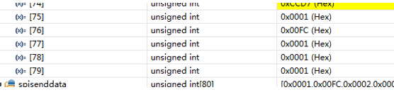
issue is the start address is not align with the setting: 0001 00FC 0001 0001 should allocated at 0x0001A800 but not in 0x001A821.

below is the debug result:

in the initialization the destination of DMA is *spiRecdata, which means spiRecdata[0].

the address is assigned in the .cmd file 

TO_CPU1_INTERNALSPI      : origin = 0x01A800, length = 0x000600 

#pragma DATA_SECTION(spiRecdata, "tOCPU1_SPI"); // map the RX data to memory
Uint16 spiRecdata[80];

it is align with DMA ADDR_SHADOW

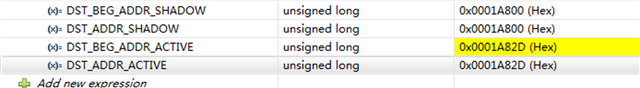
But in the debug DST_BEG_ADDR_ACTIVE changes randomly which leads to the destination start address moves to spiRecdata[75], but not spiRecdata[0]

is there some guidance to debug this issue?

Thanks

Joe

  • Hi team

    could you please kindly update this question. 

    thanks

    joe

  • Hi Joe,

    Can you verify in the map file or Expressions view that spiRecdata is actually being placed at 0x01A800? The DATA_SECTION pragma just tells the linker that you want it placed in the TO_CPU1_INTERNALSPI memory range, it doesn't necessarily put it at the beginning of the range. 

    Best Regards,

    Delaney

  • Hi Delaney

    I debug this issue in customer side, I think the root cause is DMA and SPI operation logic, I do the below change to make the code run properly:

    There left one issue need your suggestion.

    In SPI slave:

    I set DMA(receive) to continues mode, and start DMA(receive)  before timer init, timer is to control GPIO toggle. In SPI master program, GPIO toggle will trigger SPI master send and receive data.

    In SPI master:

    I set DMA(receive)  to one shot mode, and use GPIO interrupt to trigger SPI master send and enable DMA(receive)  to get SPI data sent by slave.

    with the design above, SPI slave and master will sent and receive the data at the same time SPI and DMA work properly. the target is to send 60 words per cycle.

    the SPI and DMA configuration code is below:

    DMACH6AddrConfig(DMADest,&SpiaRegs.SPIRXBUF);
    DMACH6BurstConfig(1,0,1);
    DMACH6TransferConfig(29,0,1);

    DMACH6WrapConfig(0,0,29,0);

    DMACH6ModeConfig(DMA_SPIARX,PERINT_ENABLE,ONESHOT_DISABLE,CONT_DISABLE,
    SYNC_DISABLE,SYNC_SRC,OVEFLOW_ENABLE,SIXTEEN_BIT,
    CHINT_END,CHINT_ENABLE);

    SpiaRegs.SPIFFRX.all=0x2040; // RX FIFO enabled, clear FIFO int
    SpiaRegs.SPIFFRX.bit.RXFFIL = 2;

    But the receive data will be unstable (wrong order) in some test:

    the data order should be 0x0001 0x00FC 0x0002 0x0002... but you can see in this picture, the 0x0001 0x00FC... goes to the 17th position. and sometimes SPI overflow register is set to 1.

    Is there any insight for this issue?

    Thanks

    Joe

  • Hi Joe,

    DMACH6AddrConfig(DMADest,&SpiaRegs.SPIRXBUF);
    DMACH6BurstConfig(1,0,1);
    DMACH6TransferConfig(29,0,1);

    DMACH6WrapConfig(0,0,29,0);

    DMACH6ModeConfig(DMA_SPIARX,PERINT_ENABLE,ONESHOT_DISABLE,CONT_DISABLE,
    SYNC_DISABLE,SYNC_SRC,OVEFLOW_ENABLE,SIXTEEN_BIT,
    CHINT_END,CHINT_ENABLE);

    SpiaRegs.SPIFFRX.all=0x2040; // RX FIFO enabled, clear FIFO int
    SpiaRegs.SPIFFRX.bit.RXFFIL = 2;

    Which device do these settings refer to? The master SPI device or the slave SPI device?

    It is good that the burst size (2) equals the SPI RX FIFO trigger level (2/16), and the SPI RX trigger is being used. However, you don't want to have one-shot mode enabled in this case, you want each FIFO level trigger to only transfer 2 words (a single burst) otherwise you will see data loss or strange issues like this.

    It may be helpful to look at the 18.3.8 SPI DMA Transfers section of the device TRM for some more information about how to configure the DMA to work with SPI.

    Best Regards,

    Delaney

  • Hi Delaney:

    The code is to set SPI slave receive data.

    Thanks for your suggestion will let customer change the SPI master DMA setting and test.

    One problem: I do not see the SPI_ex5 which mentioned in TRM for SPI DMA. the sdk version is 5.02 and 5.04.

    Thanks

    Joe

  • Hi Joe,

    This example actually wasn't made for the F2837xD so you will have to look under a different device's folder to find it. Try the C2000ware path: [C2000ware install]/driverlib/f28p65x/examples/cpu1/spi/spi_ex5_loopback_dma. That example is made for F28P65x, but the SPI and DMA modules across the devices are the same so they should still be able to use the example.

    Also, I will be out of office for the holidays until 12/30 so I won't be able to provide any more support until after that day. Apologies for any inconvenience.

    Best Regards,

    Delaney

  • Hi Delaney

    This solved my issue.

    Thanks

    joe