Because of the holidays, TI E2E™ design support forum responses will be delayed from Dec. 25 through Jan. 2. Thank you for your patience.

TMS320F28P550SJ: Why does the ADC reading value read 280?

Part Number: TMS320F28P550SJ
Other Parts Discussed in Thread: SYSCONFIG

Tool/software:

Hi Expert,

When we implemented ADC-related tests on TI LaunchPad, we found that

When we select the ADC reference voltage to be provided internally (3.3V)

When reading the value, I found that the measured voltage needs to be greater than half of the reference voltage (above 1.65v) before the reading value starts to change (the changed value looks correct)

But when the measured voltage is less than half of the reference voltage, the reading value will remain at about 280 (even when the measured voltage = 0)

I have tried several different sets of ADC pins with the same result.

Currently, a set of PWM is used to trigger each ADC reading.

Thanks

Daniel

  • Hey Daniel,

    Can you provide us with more information regarding your ADC configuration? (Perhaps include configuration code/sysconfig screenshots)

    Did you start from a given example project?

    One experiment worth trying out is to source the 3.3V VREFHI externally and determine if the issue persists regardless of ADC Internal/External VREF selection.

    Best Regards,

    Zackary Fleenor

  • Hi Fleenor

    Yes, we did start with TI example project (adc_ex2_epwm_tempsensor) and tried to play around with adding more ADC channels.

    Please find the attached for the source code that we are currently debugging with. Any comments will help.


    Meanwhile I will also try applying 3.3V voltage to the VREFHI and switch to external reference voltage for ADC to see if any difference.


    adc_ex2_epwm_tempsensor.c
    //###########################################################################
    //
    // FILE:   adc_ex2_epwm_tempsensor.c
    //
    // TITLE:  Sample temperature sensor and convert to temperature
    //
    //! \addtogroup bitfield_example_list
    //! <h1> ADC temperature sensor conversion</h1>
    //!
    //! This example sets up the ePWM to periodically trigger the ADC. The
    //! ADC converts the internal connection to the temperature sensor,
    //! which is then interpreted as a temperature by calling the
    //! GetTemperatureC function.
    //!
    //! After the program runs, the memory will contain:\n
    //! - \b sensorSample \b : The raw reading from the temperature sensor. \n
    //! - \b sensorTemp \b : The interpretation of the sensor sample as a
    //! temperature in degrees Celsius.
    //!
    //
    //#############################################################################
    //
    //
    // 
    // C2000Ware v5.04.00.00
    //
    // Copyright (C) 2024 Texas Instruments Incorporated - http://www.ti.com
    //
    // Redistribution and use in source and binary forms, with or without 
    // modification, are permitted provided that the following conditions 
    // are met:
    // 
    //   Redistributions of source code must retain the above copyright 
    //   notice, this list of conditions and the following disclaimer.
    // 
    //   Redistributions in binary form must reproduce the above copyright
    //   notice, this list of conditions and the following disclaimer in the 
    //   documentation and/or other materials provided with the   
    //   distribution.
    // 
    //   Neither the name of Texas Instruments Incorporated nor the names of
    //   its contributors may be used to endorse or promote products derived
    //   from this software without specific prior written permission.
    // 
    // THIS SOFTWARE IS PROVIDED BY THE COPYRIGHT HOLDERS AND CONTRIBUTORS 
    // "AS IS" AND ANY EXPRESS OR IMPLIED WARRANTIES, INCLUDING, BUT NOT 
    // LIMITED TO, THE IMPLIED WARRANTIES OF MERCHANTABILITY AND FITNESS FOR
    // A PARTICULAR PURPOSE ARE DISCLAIMED. IN NO EVENT SHALL THE COPYRIGHT 
    // OWNER OR CONTRIBUTORS BE LIABLE FOR ANY DIRECT, INDIRECT, INCIDENTAL, 
    // SPECIAL, EXEMPLARY, OR CONSEQUENTIAL DAMAGES (INCLUDING, BUT NOT 
    // LIMITED TO, PROCUREMENT OF SUBSTITUTE GOODS OR SERVICES; LOSS OF USE,
    // DATA, OR PROFITS; OR BUSINESS INTERRUPTION) HOWEVER CAUSED AND ON ANY
    // THEORY OF LIABILITY, WHETHER IN CONTRACT, STRICT LIABILITY, OR TORT 
    // (INCLUDING NEGLIGENCE OR OTHERWISE) ARISING IN ANY WAY OUT OF THE USE 
    // OF THIS SOFTWARE, EVEN IF ADVISED OF THE POSSIBILITY OF SUCH DAMAGE.
    // $
    //#############################################################################
    
    //
    // Included Files
    //
    #include "f28x_project.h"
    #include <stdarg.h> // For va_list, va_start, va_end
    #include <stdio.h> // For vsnprintf
    //
    // Defines
    //
    #define RESULTS_BUFFER_SIZE     256
    #define BUFFER_SIZE 128
    #define TIMER_PERIOD 1000000 // �w�ɾ��g���A��쬰�L��
    #define PWM_PERIOD 278
    //
    // Globals
    //
    uint16_t sensorSample = 0;
    uint16_t isrCount = 0;
    int16_t sensorTemp = 0;
    int16_t ADC1_raw=0;
    int16_t ADC2_raw=0;
    
    //
    // Function Prototypes
    //
    void initADC(void);
    void initEPWM6(void);
    void initEPWM1(void);
    void initADCSOC(void);
    __interrupt void adcC1ISR(void);
    __interrupt void adcB1ISR(void);
    __interrupt void adcA1ISR(void);
    __interrupt void cpuTimer0ISR(void);
    void initSCIAEchoback(void);
    void transmitSCIAChar(uint16_t a);
    void transmitSCIAMessage(unsigned char * msg);
    void initSCIAFIFO(void);
    
    void sciPrintf(const char *format, ...);
    void InitTimer(void);
    
    volatile Uint32 timerCount = 0;
    //
    // Main
    //
    void main(void)
    {
        //
        // Initialize device clock and peripherals
        //
        InitSysCtrl();
    
        //
        // Initialize GPIO
        //
        InitGpio();
        GPIO_SetupPinMux(28, GPIO_MUX_CPU1, 1);
        GPIO_SetupPinOptions(28, GPIO_INPUT, GPIO_PUSHPULL);
        GPIO_SetupPinMux(29, GPIO_MUX_CPU1, 1);
        GPIO_SetupPinOptions(29, GPIO_OUTPUT, GPIO_ASYNC);
        initSCIAFIFO();                         // Initialize the SCI FIFO
        initSCIAEchoback();                     // Initialize SCI for echoback
    
        sciPrintf("\r\n\n\n ADC Enabler! Test V001 \0");
    
        InitTimer(); // ��l�Ʃw�ɾ�
        //
        // Disable CPU interrupts
        //
        DINT;
    
    
        InitPieCtrl();
    
        //
        // Disable CPU interrupts and clear all CPU interrupt flags:
        //
        IER = 0x0000;
        IFR = 0x0000;
    
        //
        // Initialize the PIE vector table with pointers to the shell Interrupt
        // Service Routines (ISR).
        //
        InitPieVectTable();
    
        //
        // Map ISR functions
        //
        EALLOW;
        PieVectTable.TIMER0_INT = &cpuTimer0ISR;
        PieVectTable.ADCC1_INT = &adcC1ISR;     // Function for ADCC interrupt 1
        PieVectTable.ADCB1_INT = &adcB1ISR;
        PieVectTable.ADCA1_INT = &adcA1ISR;
        EDIS;
    
        //
        // Configure the ADC and power it up
        //
        initADC();
    
        //
        // Configure the ePWM
        //
        initEPWM1();
        PieCtrlRegs.PIEIER1.bit.INTx3 = 1;
        //
        // Setup the ADC for ePWM triggered conversions on channel 1
        //
        initADCSOC();
    
    
        EALLOW;
    
    
        //CpuSysRegs.PCLKCR0.bit.TBCLKSYNC = 1;
        InitCpuTimers();
        ConfigCpuTimer(&CpuTimer0, 150, 1000000); // 150MHz CPU Freq, 1 second Period (in uSeconds)
        CpuTimer0Regs.TCR.all = 0x4000;
    
        //
        // Enable global Interrupts and higher priority real-time debug events:
        //
        IER |= M_INT1;  // Enable group 1 interrupts
        //IER |= M_INT10;  // Enable group 1 interrupts
        PieCtrlRegs.PIEIER1.bit.INTx7 = 1;
        PieCtrlRegs.PIEIER1.bit.INTx3 = 1;
        PieCtrlRegs.PIEIER1.bit.INTx2 = 1; // �ҥβ� 1 �� ADCB ���_
        PieCtrlRegs.PIEIER1.bit.INTx1 = 1; // �ҥβ� 1 �� ADCA ���_
        EINT;           // Enable Global interrupt INTM
        ERTM;           // Enable Global realtime interrupt DBGM
    
        //InitTempSensor(3.3f);
    
        //
        // Start ePWM
        //
        EPwm1Regs.ETSEL.bit.SOCAEN = 1;    // Enable SOCA
        EPwm1Regs.TBCTL.bit.CTRMODE = 2;   // Unfreeze, and enter up count mode
        //EPwm6Regs.ETSEL.bit.SOCAEN = 1;    // Enable SOCA
         //   EPwm6Regs.TBCTL.bit.CTRMODE = 0;   // Unfreeze, and enter up count mode
    
        //
        // Wait while ePWM causes ADC conversions, which then cause interrupts,
        // which fill the results buffer, eventually setting the bufferFull
        // flag
        //
        while(1)
        {
    
        }
    }
    
    //
    // initADC - Function to configure and power up ADCC.
    //
    void initADC(void)
    {
        //
        // Setup VREF as internal
        //
        SetVREF(ADC_ADCC, ADC_INTERNAL, ADC_VREF2P5);
        SetVREF(ADC_ADCB, ADC_INTERNAL, ADC_VREF2P5);
        SetVREF(ADC_ADCA, ADC_INTERNAL, ADC_VREF2P5);
        EALLOW;
    
        //
        // Set ADCCLK divider to /4
        //
        AdccRegs.ADCCTL2.bit.PRESCALE = 6;
        AdcbRegs.ADCCTL2.bit.PRESCALE = 6;
        AdcaRegs.ADCCTL2.bit.PRESCALE = 6;
    
    
        //
        // Set pulse positions to late EOC
        //
        AdccRegs.ADCCTL1.bit.INTPULSEPOS = 1;
        AdcbRegs.ADCCTL1.bit.INTPULSEPOS = 1;
        AdcaRegs.ADCCTL1.bit.INTPULSEPOS = 1;
        //
        // Power up the ADC and then delay for 1 ms
        //
        AdccRegs.ADCCTL1.bit.ADCPWDNZ = 1;
        AdcbRegs.ADCCTL1.bit.ADCPWDNZ = 1;
        AdcaRegs.ADCCTL1.bit.ADCPWDNZ = 1;
        EDIS;
    
        DELAY_US(1000);
    }
    
    //
    // initEPWM - Function to configure ePWM1 to generate the SOC.
    //
    void initEPWM6(void)
    {
        EALLOW;
        CpuSysRegs.PCLKCR2.bit.EPWM1 = 1;
        //�t�m PWM �޸}
        InitEPwm1Gpio();
               // �t�m EPWM1 �Ѽ�
         EPwm1Regs.TBPRD = 30000;//PWM_PERIOD - 1; // PWM �g��
         EPwm1Regs.TBCTL.bit.CTRMODE = TB_COUNT_UPDOWN;//TB_COUNT_UP; // �]�w���V�W�p�ƼҦ�
    
    
               EPwm1Regs.AQCTLA.bit.ZRO = AQ_CLEAR;
    
        EPwm6Regs.ETSEL.bit.SOCAEN = 0;     // Disable SOC on A group
        EPwm6Regs.ETSEL.bit.SOCASEL = 4;    // Select SOC on up-count
        EPwm6Regs.ETPS.bit.SOCAPRD = 1;     // Generate pulse on 1st event
    
        //EPwm6Regs.CMPA.bit.CMPA = 0x0800;   // Set compare A value to 2048 counts
       // EPwm6Regs.TBPRD = 0x1000;           // Set period to 4096 counts
    
       // EPwm6Regs.TBCTL.bit.CTRMODE = 3;    // Freeze counter
    
        EDIS;
    }
    void initEPWM1(void)
    {
        EALLOW;
        CpuSysRegs.PCLKCR2.bit.EPWM1 = 1;
        InitEPwm1Gpio();
    
        EPwm1Regs.TBPRD = PWM_PERIOD - 1; // PWM �g��
        EPwm1Regs.TBCTL.bit.CTRMODE = TB_COUNT_UP;//TB_COUNT_UPDOWN;//TB_COUNT_UP; // �]�w���V�W�p�ƼҦ�
        EPwm1Regs.CMPA.bit.CMPA = 100;
        EPwm1Regs.AQCTLA.bit.CAU = AQ_CLEAR;//AQ_SET; // ��p�ƾ����� CMPA �ɳ]�m PWM �H��
        EPwm1Regs.AQCTLA.bit.CAD = AQ_SET;//AQ_CLEAR; // ��p�ƾ����� PWM �g���ɲM�� PWM �H��
    
        EPwm1Regs.ETSEL.bit.SOCAEN = 1;     // Disable SOC on A group
        EPwm1Regs.ETSEL.bit.SOCASEL = 4;    // Select SOC on up-count
        EPwm1Regs.ETPS.bit.SOCAPRD = 1;     // Generate pulse on 1st event
    
    
        EDIS;
    }
    
    //
    // initADCSOC - Function to configure ADCA's SOC0 to be triggered by ePWM1.
    //
    void initADCSOC(void)
    {
        //
        // Select the channels to convert and the end of conversion flag
        //
        EALLOW;
    
        AdccRegs.ADCSOC0CTL.bit.CHSEL = 12;     // SOC0 will convert pin C12
        AdccRegs.ADCSOC0CTL.bit.ACQPS = 63;//45;     // Sample window is 10 SYSCLK cycles
        AdccRegs.ADCSOC0CTL.bit.TRIGSEL = 5;   // Trigger on ePWM1 SOCA
        AdccRegs.ADCINTSEL1N2.bit.INT1SEL = 0; // End of SOC0 will set INT1 flag
        AdccRegs.ADCINTSEL1N2.bit.INT1E = 1;   // Enable INT1 flag
        AdccRegs.ADCINTFLGCLR.bit.ADCINT1 = 1; // Make sure INT1 flag is cleared
        AdccRegs.ADCSOC0CTL.bit.SAMPCAPRESETDISABLE = 0;
    
        // �t�m ADCB SOC0 �ഫ�M���_
        AdcbRegs.ADCSOC0CTL.bit.CHSEL = 0;
        AdcbRegs.ADCSOC0CTL.bit.ACQPS = 63;//45;
        AdcbRegs.ADCSOC0CTL.bit.TRIGSEL = 5;
        AdcbRegs.ADCINTSEL1N2.bit.INT1SEL = 0;
        AdcbRegs.ADCINTSEL1N2.bit.INT1E = 1;
        AdcbRegs.ADCINTFLGCLR.bit.ADCINT1 = 1;
        AdcbRegs.ADCSOC0CTL.bit.SAMPCAPRESETDISABLE = 0;
        // �t�m ADCA SOC0 �ഫ�M���_
        AdcaRegs.ADCSOC0CTL.bit.CHSEL = 10;
        AdcaRegs.ADCSOC0CTL.bit.ACQPS = 63;//45;
        AdcaRegs.ADCSOC0CTL.bit.TRIGSEL = 5;
        AdcaRegs.ADCINTSEL1N2.bit.INT1SEL = 0;
        AdcaRegs.ADCINTSEL1N2.bit.INT1E = 1;
        AdcaRegs.ADCINTFLGCLR.bit.ADCINT1 = 1;
        AdcaRegs.ADCSOC0CTL.bit.SAMPCAPRESETDISABLE = 0;
        EDIS;
    }
    
    //
    // adcC1ISR - ADC C Interrupt 1 ISR
    //
    __interrupt void adcC1ISR(void)
    {
    
        //isrCount++;
    
        sensorSample  = AdccResultRegs.ADCRESULT0;
        sensorTemp = GetTemperatureC(sensorSample);
    
    
        AdccRegs.ADCINTFLGCLR.bit.ADCINT1 = 1;
    
        if(1 == AdccRegs.ADCINTOVF.bit.ADCINT1)
        {
            //sciPrintf("ADC C buffer full\r\n");
            AdccRegs.ADCINTOVFCLR.bit.ADCINT1 = 1; //clear INT1 overflow flag
            AdccRegs.ADCINTFLGCLR.bit.ADCINT1 = 1; //clear INT1 flag
        }
    
        PieCtrlRegs.PIEACK.all = PIEACK_GROUP1;
    }
    __interrupt void adcB1ISR(void)
    {
    
        //isrCount++;
    
        ADC2_raw  = AdcbResultRegs.ADCRESULT0;
        //sensorTemp = GetTemperatureC(sensorSample);
    
    
        AdcbRegs.ADCINTFLGCLR.bit.ADCINT1 = 1;
    
        if(1 == AdcbRegs.ADCINTOVF.bit.ADCINT1)
        {
           // sciPrintf("ADC B buffer full\r\n");
            AdcbRegs.ADCINTOVFCLR.bit.ADCINT1 = 1; //clear INT1 overflow flag
            AdcbRegs.ADCINTFLGCLR.bit.ADCINT1 = 1; //clear INT1 flag
        }
    
        PieCtrlRegs.PIEACK.all = PIEACK_GROUP1;
    }
    __interrupt void adcA1ISR(void)
    {
    
        //isrCount++;
    
        ADC1_raw  = AdcaResultRegs.ADCRESULT0;
        //sensorTemp = GetTemperatureC(sensorSample);
    
    
        AdcaRegs.ADCINTFLGCLR.bit.ADCINT1 = 1;
    
        if(1 == AdcaRegs.ADCINTOVF.bit.ADCINT1)
        {
            //sciPrintf("ADC A buffer full\r\n");
            AdcaRegs.ADCINTOVFCLR.bit.ADCINT1 = 1; //clear INT1 overflow flag
            AdcaRegs.ADCINTFLGCLR.bit.ADCINT1 = 1; //clear INT1 flag
        }
    
        PieCtrlRegs.PIEACK.all = PIEACK_GROUP1;
    }
    void initSCIAEchoback(void)
    {
        //
        // Note: Clocks were turned on to the SCIA peripheral
        // in the InitSysCtrl() function
        //
        SciaRegs.SCICCR.all = 0x0007;           // 1 stop bit,  No loopback
                                                // No parity, 8 char bits,
                                                // async mode, idle-line protocol
        SciaRegs.SCICTL1.all = 0x0003;          // enable TX, RX, internal SCICLK,
                                                // Disable RX ERR, SLEEP, TXWAKE
        SciaRegs.SCICTL2.all = 0x0003;
        SciaRegs.SCICTL2.bit.TXINTENA = 1;
        SciaRegs.SCICTL2.bit.RXBKINTENA = 1;
    
        //
        // SCIA at 9600 baud
        // @LSPCLK = 37.5 MHz (150 MHz SYSCLK) HBAUD = 0x01 and LBAUD = 0xE7.
        //
        SciaRegs.SCIHBAUD.all = 0x0001;
        SciaRegs.SCILBAUD.all = 0x00E7;
    
        SciaRegs.SCICTL1.all = 0x0023;          // Relinquish SCI from Reset
    }
    
    //
    // transmitSCIAChar - Transmit a character from the SCI
    //
    void transmitSCIAChar(uint16_t a)
    {
        while (SciaRegs.SCIFFTX.bit.TXFFST != 0)
        {
    
        }
        SciaRegs.SCITXBUF.all = a;
    }
    
    //
    // transmitSCIAMessage - Transmit message via SCIA
    //
    void transmitSCIAMessage(unsigned char * msg)
    {
        int i;
        i = 0;
        while(msg[i] != '\0')
        {
            transmitSCIAChar(msg[i]);
            i++;
        }
    }
    
    //
    // initSCIAFIFO - Initialize the SCI FIFO
    //
    void initSCIAFIFO(void)
    {
        SciaRegs.SCIFFTX.all = 0xE040;
        SciaRegs.SCIFFRX.all = 0x2044;
        SciaRegs.SCIFFCT.all = 0x0;
    }
    void sciPrintf(const char *format, ...)
    {
        char buffer[BUFFER_SIZE];
        int i;
        va_list args;
        va_start(args, format);
        vsnprintf(buffer, BUFFER_SIZE, format, args);
        va_end(args);
        for (i = 0; buffer[i] != '\0'; i++)
        {
            transmitSCIAChar(buffer[i]);
        }
    }
    void InitTimer(void)
    {
        sciPrintf("InitTimer\r\n");
        ConfigCpuTimer(&CpuTimer0, 200, TIMER_PERIOD);
        CpuTimer0Regs.TCR.all = 0x4000;
    }
    
    
    __interrupt void cpuTimer0ISR(void)
    {
    
    
        sciPrintf("ADC C value= %d\r\n",sensorSample);
        sciPrintf("ADC A value= %d\r\n",ADC1_raw);
        sciPrintf("ADC B value= %d\r\n",ADC2_raw);
        sensorSample=0;
        ADC1_raw=0;
        ADC2_raw=0;
    
       // sciPrintf("Temperature= %d\r\n",sensorTemp);
    
    
        CpuTimer0Regs.TCR.bit.TIF = 1;
    
        PieCtrlRegs.PIEACK.all = PIEACK_GROUP1;
    }
    //
    // End of file
    //
    

    Thanks

    Daniel

  • Hey Daniel,

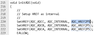
    One thing I noticed in your initADC() function is that you are using 2.5V Vref. Can you change this to ADC_VREF3P3 and provide your findings?

    Best Regards,

    Zackary Fleenor

  • Hi Fleenor

    I have already tried both ADC_INTERNAL (2P5/3P3), ADC_EXTERNAL (3P3) and had observed the same bahavior.
    The ADC reading will keep unchanged until the apllied voltage for measurement exceed around1.6V.

    I have obseved another strange behavior.
    The ADC reading seems to related to the PWM duty.
    If I set the PWM duty to 1, the ADC reading start to change at applied voltage exceed 2.8V.
    If I set the PWM duty to 200, the ADC reading start to change at applied voltage exceed 0.9V.

    Thanks

    Daniel

  • Hey Daniel,

    I am currently unable to replicate this issue on my end. Can you please start with a brand-new copy of adc_ex3_temp_sensor and provide us with your observations (with all three VREF options)? Then we can look at what changes may have been made to cause the issue you are facing when measuring other analog input signals as well.

    Best Regards,

    Zackary Fleenor

  • Hi Fleenor

    We have started a new copy of adc_ex1_soc_epwm.

    Only thing I have done was to modify the ADC from ADC A1 to A10. Add printf function and enable timer to output the ADC reading in the time interval of 1s.

    And we have observed the same issue. The ADC reading only start to change after the applied voltage exceed certain level.

    Please find the source code attached.

    Thanks

    adc_ex1_soc_epwm.c
    //#############################################################################
    //
    // FILE:   adc_ex1_soc_epwm.c
    //
    // TITLE:  ADC ePWM Triggering
    //
    //! \addtogroup bitfield_example_list
    //! <h1>ADC ePWM Triggering</h1>
    //!
    //! This example sets up ePWM1 to periodically trigger a conversion on ADCA.
    //!
    //! \b External \b Connections \n
    //!  - A1 should be connected to a signal to convert
    //!
    //! \b Watch \b Variables \n
    //! - \b adcAResults - A sequence of analog-to-digital conversion samples from
    //!   pin A1. The time between samples is determined based on the period
    //!   of the ePWM timer.
    //!
    //
    //#############################################################################
    //
    //
    // 
    // C2000Ware v5.04.00.00
    //
    // Copyright (C) 2024 Texas Instruments Incorporated - http://www.ti.com
    //
    // Redistribution and use in source and binary forms, with or without 
    // modification, are permitted provided that the following conditions 
    // are met:
    // 
    //   Redistributions of source code must retain the above copyright 
    //   notice, this list of conditions and the following disclaimer.
    // 
    //   Redistributions in binary form must reproduce the above copyright
    //   notice, this list of conditions and the following disclaimer in the 
    //   documentation and/or other materials provided with the   
    //   distribution.
    // 
    //   Neither the name of Texas Instruments Incorporated nor the names of
    //   its contributors may be used to endorse or promote products derived
    //   from this software without specific prior written permission.
    // 
    // THIS SOFTWARE IS PROVIDED BY THE COPYRIGHT HOLDERS AND CONTRIBUTORS 
    // "AS IS" AND ANY EXPRESS OR IMPLIED WARRANTIES, INCLUDING, BUT NOT 
    // LIMITED TO, THE IMPLIED WARRANTIES OF MERCHANTABILITY AND FITNESS FOR
    // A PARTICULAR PURPOSE ARE DISCLAIMED. IN NO EVENT SHALL THE COPYRIGHT 
    // OWNER OR CONTRIBUTORS BE LIABLE FOR ANY DIRECT, INDIRECT, INCIDENTAL, 
    // SPECIAL, EXEMPLARY, OR CONSEQUENTIAL DAMAGES (INCLUDING, BUT NOT 
    // LIMITED TO, PROCUREMENT OF SUBSTITUTE GOODS OR SERVICES; LOSS OF USE,
    // DATA, OR PROFITS; OR BUSINESS INTERRUPTION) HOWEVER CAUSED AND ON ANY
    // THEORY OF LIABILITY, WHETHER IN CONTRACT, STRICT LIABILITY, OR TORT 
    // (INCLUDING NEGLIGENCE OR OTHERWISE) ARISING IN ANY WAY OUT OF THE USE 
    // OF THIS SOFTWARE, EVEN IF ADVISED OF THE POSSIBILITY OF SUCH DAMAGE.
    // $
    //#############################################################################
    
    //
    // Included Files
    //
    #include "f28x_project.h"
    #include <stdarg.h> // For va_list, va_start, va_end
    #include <stdio.h> // For vsnprintf
    //
    // Defines
    //
    #define RESULTS_BUFFER_SIZE     256
    #define BUFFER_SIZE 128
    #define TIMER_PERIOD 1000000 // �w�ɾ��g���A��쬰�L��
    #define PWM_PERIOD 278
    //
    // Globals
    //
    uint16_t adcAResults[RESULTS_BUFFER_SIZE];   // Buffer for results
    uint16_t index;                              // Index into result buffer
    volatile uint16_t bufferFull;                // Flag to indicate buffer is full
    
    //
    // Function Prototypes
    //
    void initADC(void);
    void initEPWM(void);
    void initADCSOC(void);
    __interrupt void adcA1ISR(void);
    __interrupt void cpuTimer0ISR(void);
    
    void initSCIAEchoback(void);
    void transmitSCIAChar(uint16_t a);
    void transmitSCIAMessage(unsigned char * msg);
    void initSCIAFIFO(void);
    
    void sciPrintf(const char *format, ...);
    void InitTimer(void);
    
    volatile Uint32 timerCount = 0;
    uint16_t sensorSample = 0;
    uint16_t isrCount = 0;
    int16_t sensorTemp = 0;
    //
    // Main
    //
    void main(void)
    {
        //
        // Initialize device clock and peripherals
        //
        InitSysCtrl();
    
        //
        // Initialize GPIO
        //
        InitGpio();
        GPIO_SetupPinMux(28, GPIO_MUX_CPU1, 1);
            GPIO_SetupPinOptions(28, GPIO_INPUT, GPIO_PUSHPULL);
            GPIO_SetupPinMux(29, GPIO_MUX_CPU1, 1);
            GPIO_SetupPinOptions(29, GPIO_OUTPUT, GPIO_ASYNC);
            initSCIAFIFO();                         // Initialize the SCI FIFO
            initSCIAEchoback();                     // Initialize SCI for echoback
            sciPrintf("\r\n\n\n ADC Enabler! Test V002 \0");
            InitTimer(); // ��l�Ʃw�ɾ�
        //
        // Disable CPU interrupts
        //
        DINT;
    
        //
        // Initialize the PIE control registers to their default state.
        // The default state is all PIE interrupts disabled and flags
        // are cleared.
        //
        InitPieCtrl();
    
        //
        // Disable CPU interrupts and clear all CPU interrupt flags:
        //
        IER = 0x0000;
        IFR = 0x0000;
    
        //
        // Initialize the PIE vector table with pointers to the shell Interrupt
        // Service Routines (ISR).
        //
        InitPieVectTable();
    
        //
        // Map ISR functions
        //
        EALLOW;
        PieVectTable.ADCA1_INT = &adcA1ISR;     // Function for ADCA interrupt 1
        PieVectTable.TIMER0_INT = &cpuTimer0ISR;
        EDIS;
    
        //
        // Configure the ADC and power it up
        //
        initADC();
    
        //
        // Configure the ePWM
        //
        initEPWM();
    
        //
        // Setup the ADC for ePWM triggered conversions on channel 1
        //
        initADCSOC();
        InitCpuTimers();
            ConfigCpuTimer(&CpuTimer0, 150, 1000000); // 150MHz CPU Freq, 1 second Period (in uSeconds)
            CpuTimer0Regs.TCR.all = 0x4000;
        //
        // Enable global Interrupts and higher priority real-time debug events:
        //
        IER |= M_INT1;  // Enable group 1 interrupts
    
        EINT;           // Enable Global interrupt INTM
        ERTM;           // Enable Global realtime interrupt DBGM
    
        //
        // Initialize results buffer
        //
        for(index = 0; index < RESULTS_BUFFER_SIZE; index++)
        {
            adcAResults[index] = 0;
        }
    
        index = 0;
        bufferFull = 0;
    
        //
        // Enable PIE interrupt
        //
        PieCtrlRegs.PIEIER1.bit.INTx1 = 1;
        PieCtrlRegs.PIEIER1.bit.INTx7 = 1;
        //
        // Sync ePWM
        //
        EALLOW;
        CpuSysRegs.PCLKCR0.bit.TBCLKSYNC = 1;
    
        //
        // Take conversions indefinitely in loop
        //
        while(1)
        {
            //
            // Start ePWM
            //
            EPwm1Regs.ETSEL.bit.SOCAEN = 1;    // Enable SOCA
            EPwm1Regs.TBCTL.bit.CTRMODE = 0;   // Unfreeze, and enter up count mode
    
            //
            // Wait while ePWM causes ADC conversions, which then cause interrupts,
            // which fill the results buffer, eventually setting the bufferFull
            // flag
            //
            while(!bufferFull)
            {
            }
            bufferFull = 0; //clear the buffer full flag
    
            //
            // Stop ePWM
            //
            EPwm1Regs.ETSEL.bit.SOCAEN = 0;    // Disable SOCA
            EPwm1Regs.TBCTL.bit.CTRMODE = 3;   // Freeze counter
    
            //
            // Software breakpoint. At this point, conversion results are stored in
            // adcAResults.
            //
            // Hit run again to get updated conversions.
            //
           // ESTOP0;
        }
    }
    
    //
    // initADC - Function to configure and power up ADCA.
    //
    void initADC(void)
    {
        //
        // Setup VREF as internal
        //
        SetVREF(ADC_ADCA, ADC_INTERNAL, ADC_VREF3P3);
    
        EALLOW;
    
        //
        // Set ADCCLK divider to /4
        //
        AdcaRegs.ADCCTL2.bit.PRESCALE = 6;
    
        //
        // Set pulse positions to late
        //
        AdcaRegs.ADCCTL1.bit.INTPULSEPOS = 1;
    
        //
        // Power up the ADC and then delay for 1 ms
        //
        AdcaRegs.ADCCTL1.bit.ADCPWDNZ = 1;
        EDIS;
    
        DELAY_US(1000);
    }
    
    //
    // initEPWM - Function to configure ePWM1 to generate the SOC.
    //
    void initEPWM(void)
    {
        EALLOW;
    
        EPwm1Regs.ETSEL.bit.SOCAEN = 0;     // Disable SOC on A group
        EPwm1Regs.ETSEL.bit.SOCASEL = 4;    // Select SOC on up-count
        EPwm1Regs.ETPS.bit.SOCAPRD = 1;     // Generate pulse on 1st event
    
        EPwm1Regs.CMPA.bit.CMPA = 0x0800;   // Set compare A value to 2048 counts
        EPwm1Regs.TBPRD = 0x1000;           // Set period to 4096 counts
    
        EPwm1Regs.TBCTL.bit.CTRMODE = 3;    // Freeze counter
    
        EDIS;
    }
    
    //
    // initADCSOC - Function to configure ADCA's SOC0 to be triggered by ePWM1.
    //
    void initADCSOC(void)
    {
        //
        // Select the channels to convert and the end of conversion flag
        //
        EALLOW;
    
        AdcaRegs.ADCSOC0CTL.bit.CHSEL = 10;     // SOC0 will convert pin A10
                                               // 0:A0  1:A1  2:A2  3:A3
                                               // 4:A4   5:A5   6:A6   7:A7
                                               // 8:A8   9:A9   A:A10  B:A11
                                               // C:A12  D:A13  E:A14  F:A15
        AdcaRegs.ADCSOC0CTL.bit.ACQPS = 9;     // Sample window is 10 SYSCLK cycles
        AdcaRegs.ADCSOC0CTL.bit.TRIGSEL = 5;   // Trigger on ePWM1 SOCA
    
        AdcaRegs.ADCINTSEL1N2.bit.INT1SEL = 0; // End of SOC0 will set INT1 flag
        AdcaRegs.ADCINTSEL1N2.bit.INT1E = 1;   // Enable INT1 flag
        AdcaRegs.ADCINTFLGCLR.bit.ADCINT1 = 1; // Make sure INT1 flag is cleared
    
        EDIS;
    }
    
    //
    // adcA1ISR - ADC A Interrupt 1 ISR
    //
    __interrupt void adcA1ISR(void)
    {
        //
        // Add the latest result to the buffer
        // ADCRESULT0 is the result register of SOC0
        adcAResults[index++] = AdcaResultRegs.ADCRESULT0;
        sensorSample=adcAResults[index];
        //
        // Set the bufferFull flag if the buffer is full
        //
        if(RESULTS_BUFFER_SIZE <= index)
        {
            index = 0;
            bufferFull = 1;
        }
    
        //
        // Clear the interrupt flag
        //
        AdcaRegs.ADCINTFLGCLR.bit.ADCINT1 = 1;
    
        //
        // Check if overflow has occurred
        //
        if(1 == AdcaRegs.ADCINTOVF.bit.ADCINT1)
        {
            AdcaRegs.ADCINTOVFCLR.bit.ADCINT1 = 1; //clear INT1 overflow flag
            AdcaRegs.ADCINTFLGCLR.bit.ADCINT1 = 1; //clear INT1 flag
        }
    
        //
        // Acknowledge the interrupt
        //
        PieCtrlRegs.PIEACK.all = PIEACK_GROUP1;
    }
    void initSCIAFIFO(void)
    {
        SciaRegs.SCIFFTX.all = 0xE040;
        SciaRegs.SCIFFRX.all = 0x2044;
        SciaRegs.SCIFFCT.all = 0x0;
    }
    void initSCIAEchoback(void)
    {
        //
        // Note: Clocks were turned on to the SCIA peripheral
        // in the InitSysCtrl() function
        //
        SciaRegs.SCICCR.all = 0x0007;           // 1 stop bit,  No loopback
                                                // No parity, 8 char bits,
                                                // async mode, idle-line protocol
        SciaRegs.SCICTL1.all = 0x0003;          // enable TX, RX, internal SCICLK,
                                                // Disable RX ERR, SLEEP, TXWAKE
        SciaRegs.SCICTL2.all = 0x0003;
        SciaRegs.SCICTL2.bit.TXINTENA = 1;
        SciaRegs.SCICTL2.bit.RXBKINTENA = 1;
    
        //
        // SCIA at 9600 baud
        // @LSPCLK = 37.5 MHz (150 MHz SYSCLK) HBAUD = 0x01 and LBAUD = 0xE7.
        //
        SciaRegs.SCIHBAUD.all = 0x0001;
        SciaRegs.SCILBAUD.all = 0x00E7;
    
        SciaRegs.SCICTL1.all = 0x0023;          // Relinquish SCI from Reset
    }
    
    //
    // transmitSCIAChar - Transmit a character from the SCI
    //
    void transmitSCIAChar(uint16_t a)
    {
        while (SciaRegs.SCIFFTX.bit.TXFFST != 0)
        {
    
        }
        SciaRegs.SCITXBUF.all = a;
    }
    
    //
    // transmitSCIAMessage - Transmit message via SCIA
    //
    void transmitSCIAMessage(unsigned char * msg)
    {
        int i;
        i = 0;
        while(msg[i] != '\0')
        {
            transmitSCIAChar(msg[i]);
            i++;
        }
    }
    void sciPrintf(const char *format, ...)
    {
        char buffer[BUFFER_SIZE];
        int i;
        va_list args;
        va_start(args, format);
        vsnprintf(buffer, BUFFER_SIZE, format, args);
        va_end(args);
        for (i = 0; buffer[i] != '\0'; i++)
        {
            transmitSCIAChar(buffer[i]);
        }
    }
    
    void InitTimer(void)
    {
        sciPrintf("InitTimer\r\n");
        ConfigCpuTimer(&CpuTimer0, 200, TIMER_PERIOD);
        CpuTimer0Regs.TCR.all = 0x4000;
    }
    
    
    __interrupt void cpuTimer0ISR(void)
    {
    
    
        sciPrintf("ADC= %d\r\n",sensorSample);
    
    
        CpuTimer0Regs.TCR.bit.TIF = 1;
    
        PieCtrlRegs.PIEACK.all = PIEACK_GROUP1;
    }
    //
    // End of File
    //
    

    Daniel

  • Hey Daniel,

    Thank you for this information. I don't see anything out of the ordinary yet.

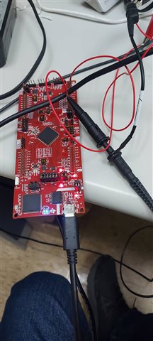
    Can you provide more details on the test setup, what instrument is being used to generate the analog input signal? Is any additional input conditioning circuitry used?

    One test that will help is to use the internal temp sensor example so we can eliminate the possibility of an issue with the physical input signal to the adc.

    Thank you for your assistance and participation while we continue to debug your issue.

    Best Regards

    Zackary Fleenor

  • Hi Fleenor

    I have tried the sample code  "adc_ex10_multiple_soc_epwm" on different pins by modifying the ADC initial.

    What I have observed is , some of the pins that actually behave as expected. While some of the pins still behave strangely.


    Pins that I have tried and behave normally are ADC A1, A4, A5, A10 and B5.

    Pins that I have tried but behave abnormally are ADC C1, C14, B11, B2, B3 and B4.


    There are must be some unknown settings on the EVK that I am not aware of.


    I will continue my FW development with those workable ADCs first

    Thanks

    Daniel