This thread has been locked.

If you have a related question, please click the "Ask a related question" button in the top right corner. The newly created question will be automatically linked to this question.

TMS320F280049C: Design/coefficient calculation of 2p2z controller parameters and their relationship with the continuous time-domain transfer function

Part Number: TMS320F280049C
Other Parts Discussed in Thread: TIDM-DC-DC-BUCK, C2000WARE

Tool/software:

Hello,

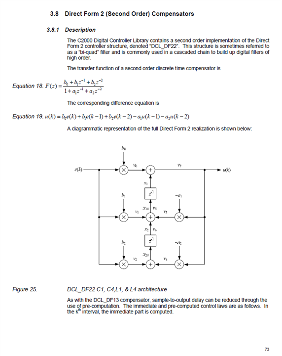
There is an ambiguity in frequency domain representation of 2p2z controller. The continuous time-domain transfer function representation mentioned in application note “Digital Peak Current Mode Control With Slope Compensation Using the TMS320F2803x” is different from the one seen in the compensator design GUI present in CCS.

Transfer Function in Application note:


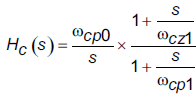
Transfer Function seen in GUI:

In the code blocks of TIDM-DC-DC-Buck, I have seen use of gain "K_DC" in definitions. However, I am unable to make co-relation between the two forms of continuous time transfer functions as both form a 2p2z controller when transformed to discrete time domain. Please clarify how a continuous time domain transfer function gets represented in discrete time domain and used in code blocks.

Thanks & Regards,

Anirudh  

  • Hi Sumit,

    Sorry but it does not answer my query.

    My question is based on the TIDM-DC-DC-Buck code. I have the following questions basically:

    a. How k_dc value is being used in the code and how it effects the performance.

    b. What is the difference in two controller designs shown in images shared (in actual post). I have seen in the transfer function without k_dc gain in the application note. 

  • a. Kdc is DC gain, that is gain at 0Hz frequency, if you see from the bode plot (gain vs frequency) presented in the user guide. It affects the DC gain performance of loop. Higher the value of this gain the better it is. It start rolling off as frequency of variation/disturbance in feedback increases.

    b. Application note show Laplace representation of transfer function of compensator vs GUI shows discrete time transfer function representation of compensator transfer function. Reference code TIDM-DC-DC-Buck uses 2-pole 2 zero compensator type whose compensation coefficient can be calculated using following equation which uses two poles and two zero frequencies.

    You can refer reference guide of digital control library located in C2000Ware at following location: ...:\ti\c2000\C2000Ware_5_02_00_00\libraries\control\DCL

    This location also includes MATLAB models to show how these compensator implemented to explore these compensation in great detail.

    Regards,

    Sumit

  • Hi Sumit,

    Thanks for the details. I now get that K_dc factor is part of coefficients b0, b1, and b2.

    I tried checking the document that you mentioned in C2000Ware_5_02_00_00 but I could not find the table that you added in the "DCL User's Guide". Let me know if it is part of any document or you have derived and placed it here.

    Thanks & Regards,

    Anirudh 

  • Anirudh,

    The used guide is located in docs subfolder as shown below:

    2p2z description is located on page 73 as shown below and defined in DCL.h of include subfolder as shown below.

    Let us know if any questions.

    Regards,

    Sumit