This thread has been locked.

If you have a related question, please click the "Ask a related question" button in the top right corner. The newly created question will be automatically linked to this question.

LAUNCHXL-F280049C: Blanking Window

Part Number: LAUNCHXL-F280049C

Tool/software:

Hi. 


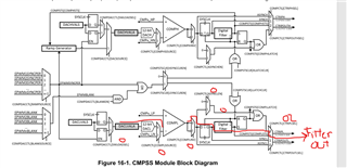
I am studying the code available for the C2000 DPS BoosterPack, and I have a question about the blanking window (I am working in open-loop VMC). This is what the CMPSS module ends up with after configuration:

  • CTRIPL goes to the EPWM X-Bar.

  • CTRIPOUTL goes to the OUTPUT X-Bar.

After configuring the trip current and the digital filtering, the code selects the EPWM1BLANK signal as the source and enables the EPWMBLANK signal.

//
// Use the Blanking signal from Sync Buck EPWM to reject switching noise
//
CMPSS_configBlanking(BUCK_OC_CMPSS_BASE, BUCK_DRV_EPWM_NUM);
CMPSS_enableBlanking(BUCK_OC_CMPSS_BASE);

Then, it configures the blanking window for the EPWM

//BUCK_DRV_EPWM_TBPRD = 499 (100MHz/200kHz -1)
//BUCK_DRV_EPWM_DC_BLANK_EARLY (5)
#define BUCK_DRV_EPWM_DC_BLANK_OFFSET      ((uint16_t)BUCK_DRV_EPWM_TBPRD - BUCK_DRV_EPWM_DC_BLANK_EARLY)//494

//BUCK_EPWM_NS = 10nS
//BUCK_DRV_EPWM_DC_BLANK_EARLY = 5
#define BUCK_DRV_EPWM_DC_BLANK_LENGTH      ((uint16_t)(190 / BUCK_EPWM_NS) + BUCK_DRV_EPWM_DC_BLANK_EARLY)//24

//
// BUCK_HAL_setupSyncBuckBlankingWindow - Use ePWM blanking window (filter) to:
//     A) Avoid boundary conditions originating from comparator trips arriving
//        near the end of ePWM cycles, and
//     B) Switching noise at the start of ePWM cycles (VMC)
//
void BUCK_HAL_setupSyncBuckBlankingWindow(void)
{
    EPWM_setDigitalCompareFilterInput(BUCK_DRV_EPWM_BASE,
                                      BUCK_DRV_EPWM_DC_BLANK_SOURCE);
    EPWM_setDigitalCompareBlankingEvent(BUCK_DRV_EPWM_BASE,
                                        BUCK_DRV_EPWM_DC_BLANK_PULSE);
    EPWM_setDigitalCompareWindowOffset(BUCK_DRV_EPWM_BASE,
                                       BUCK_DRV_EPWM_DC_BLANK_OFFSET);
    EPWM_setDigitalCompareWindowLength(BUCK_DRV_EPWM_BASE,
                                       BUCK_DRV_EPWM_DC_BLANK_LENGTH);
    EPWM_enableDigitalCompareBlankingWindow(BUCK_DRV_EPWM_BASE);
}

My questions are:

  1. In the first code, when you configure:

    • CMPSS_Reg.COMPDACCTL.BLANKSOURCE = 0

    • CMPSS_Reg.COMPDACCTL.BLANKSOURCE = 1

    Does this mean I am telling the MCU that EPWM1 will hold the trip when it occurs? Is this correct?

  2. I don’t fully understand the configuration of the blanking window. I understand that the blanking window helps DCAEVT1/2 and DCBEVT1/2 avoid glitches, false flags (e.g., overcurrent), etc. However, how do I know if CTRIPL or CTRIPOUTL corresponds to DCAEVT1?

    Checking Table 9-2, I see:

    • CMPSS1_CTRIPL = INPUTXBAR1 | CLB1_OUT12 | ADCCEVT1

    • CMPSS1_CTRIPH = ADCAEVT1

    How do I determine which signal corresponds to DCAEVT1?

  1. The blanking window configuration code selects:

    1. ePWM_Reg.DCFCTL.PULSESEL = 1 (Pulse select when TBCTR = 0x00)

    2. ePWM_Reg.DCFOFFSET = 494

    3. ePWM_Reg.DCFWINDOW = 24

    How did the code select these values? How do I determine what window value and offset are suitable for my application?

  • Hi Andres,

    Does this mean I am telling the MCU that EPWM1 will hold the trip when it occurs? Is this correct?

    If you are using DriverLib, then the function call CMPSS_configBlanking(BUCK_OC_CMPSS_BASE, BUCK_DRV_EPWM_NUM) will pass in the value from BUCK_DRV_EPWM_NUM, the default is 1, corresponding to EPWM1. 

    The blanking window is a signal originating from the EPWM Digital Compare module and used as an input to the CMPSS, notice the BLANKSOURCE in the bottom left of the CMPSS block diagram. The function call simply configures the CMPSS module to not output trip signal during EPWM blanking window. Doing it this way means you can choose different EPWM modules to generate the Blanking Window and to receive the trip output from the CMPSS. Of course you can also use the same EPWM module as is done in the DC-DC-BUCK software.

    I don’t fully understand the configuration of the blanking window. I understand that the blanking window helps DCAEVT1/2 and DCBEVT1/2 avoid glitches, false flags (e.g., overcurrent), etc. However, how do I know if CTRIPL or CTRIPOUTL corresponds to DCAEVT1?

    CTRIPOUTL is only ever connected to the OUTPUTXBAR and is primarily used for debugging purposes (e.g. display trip signal on scope). CTRIPL is the signal which is connected to the internal XBARs of the device. In this case, the CTRIPL signal would be connected to the EPWMXBAR which is then connected to the digital compare module of the EPWM

    CMPSS1_CTRIPL = INPUTXBAR1 | CLB1_OUT12 | ADCCEVT1

    This part is misinterpreted. The signals are on a single MUX, so you choose between CMPSS1_CTRIPL, INPUTXBAR1, CLB1_OUT12, or ADCCEVT1 depending on the value of the MUX. But they cannot be ORed together. In this instance, you would choose MUX G1 = 0 corresponding to the CTRIPL signal

    How did the code select these values? How do I determine what window value and offset are suitable for my application?

    Let me consult with our PWM experts to see if they've released any specific collateral for this. From my experience, these window and offset values are largely dependent on the switching frequency of your PWMs and should be fine tuned through experimentation

    Regards,

    Peter

  • Later, I realized that I misinterpreted Table 9-2. I now understand how DCAEVT1 is assigned and how to configure the respective MUX. Thanks for the explanation. It’s not easy going through 2000 pages and understanding the block diagrams to see how the signals flow.

    That’d be great. If there isn’t a guideline, could you please give me some advice on how to tune the blanking window? For what I see, we usually use the window length during the transition of HIGH -> LOW or LOW to HIGH like the project

    Let me consult with our PWM experts to see if they've released any specific collateral for this. From my experience, these window and offset values are largely dependent on the switching frequency of your PWMs and should be fine tuned through experimentation
  • Hi Andres,

    I discussed with the PWM expert, we don't have any detailed collateral regarding selecting blanking window parameters, only the Event Filtering informational section of the TRM.

    You are right on the application of the blanking window, this is usually used on each switching cycle to reduce switching noise impact on the CMPSS trips. You can configure the blanking window offset and width to occur when the PWM switches high or low. The PWM event which initiates this blanking window can be selected through the PULSESEL register. For the offset, the ideal is positioning this such that PWM switching occurs in the middle of the blanking window and the exact value of this will be based on the switching frequency and the EPWMCLK speed. The window width is really what should be tuned to your application depending on how much noise you anticipate. Having it too long would create latency in your control loop but having it too short would make the CMPSS be more susceptible to noise and negate impact of blanking window. I think width of 24 is good value to start with and you can test more from there  

    Regards,

    Peter