This thread has been locked.

If you have a related question, please click the "Ask a related question" button in the top right corner. The newly created question will be automatically linked to this question.

TMDSCNCD28379D: How to ADC setup properly?

Part Number: TMDSCNCD28379D


Tool/software:

Hi,

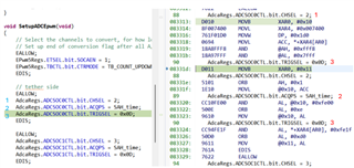
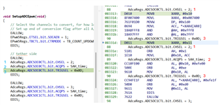
Could anyone help with this simple question but I am not clear. If my interrupt is set to ADCD1, do I need to add the EOC information and interrupt flag information under the other AdcxReg. ****, like below AdcbRegs.******, hightlighted in red?

AdcbRegs.ADCSOC0CTL.bit.CHSEL = 0;

AdcbRegs.ADCSOC0CTL.bit.ACQPS = 14;

AdcbRegs.ADCSOC0CTL.bit.TRIGSEL = 12;

AdcbRegs.ADCINTSEL1N2.bit.INT1SEL = 0;

AdcbRegs.ADCINTSEL1N2.bit.INT1E = 1;

AdcbRegs.ADCINTFLGCLR.bit.ADCINT1 = 1; 


AdcdRegs.ADCSOC0CTL.bit.CHSEL = 3;

AdcdRegs.ADCSOC0CTL.bit.ACQPS = 14;

AdcdRegs.ADCSOC0CTL.bit.TRIGSEL = 12;        

AdcdRegs.ADCINTSEL1N2.bit.INT1SEL = 0;

AdcdRegs.ADCINTSEL1N2.bit.INT1E = 1;

AdcdRegs.ADCINTFLGCLR.bit.ADCINT1 = 1;    

Thanks,

Hongmei Wan

  • If the all the ADCs are from the same trigger, then I agree that you can just use one ADC(in this case D) interrupt to then read all the results since the timing will be consistent across all the ADCs; ex when above ADCD is done, ADCB conversion will be done as well.

    Best,

    Matt

  • Hi Matt,

    Thank you very much. Could you please review the following questions?

    1. From the same trigger, ADCSOC0CLT is used for ADC conversion, one interrupt ADCD1 is used. --This is good.

    If other ADC interrupt, say ADCB1, is used, only the last three lines have to be modified, (AdcdRegs replaced by AdcbRegs if interrupt ADCB1 is used ), right?

    AdcbRegs.ADCSOC0CTL.bit.CHSEL = 0;

    AdcbRegs.ADCSOC0CTL.bit.ACQPS = 14;

    AdcbRegs.ADCSOC0CTL.bit.TRIGSEL = 12;   

    AdcdRegs.ADCSOC0CTL.bit.CHSEL = 3;

    AdcdRegs.ADCSOC0CTL.bit.ACQPS = 14;

    AdcdRegs.ADCSOC0CTL.bit.TRIGSEL = 12;       

    AdcdRegs.ADCINTSEL1N2.bit.INT1SEL = 0;

    AdcdRegs.ADCINTSEL1N2.bit.INT1E = 1;

    AdcdRegs.ADCINTFLGCLR.bit.ADCINT1 = 1; 

    2. From different triggers, ADCSOC0CLT is used for ADC conversion, one interrupt ADCD1 is used.  I have to add the lines in blue, right? Anything else needs to be done for this case?

    AdcbRegs.ADCSOC0CTL.bit.CHSEL = 0;

    AdcbRegs.ADCSOC0CTL.bit.ACQPS = 14;

    AdcbRegs.ADCSOC0CTL.bit.TRIGSEL = 10;  

    AdcbRegs.ADCINTSEL1N2.bit.INT1SEL = 0;

    AdcbRegs.ADCINTSEL1N2.bit.INT1E = 1;

    AdcbRegs.ADCINTFLGCLR.bit.ADCINT1 = 1;   

    AdcdRegs.ADCSOC0CTL.bit.CHSEL = 3;

    AdcdRegs.ADCSOC0CTL.bit.ACQPS = 14;

    AdcdRegs.ADCSOC0CTL.bit.TRIGSEL = 12;       

    AdcdRegs.ADCINTSEL1N2.bit.INT1SEL = 0;

    AdcdRegs.ADCINTSEL1N2.bit.INT1E = 1;

    AdcdRegs.ADCINTFLGCLR.bit.ADCINT1 = 1; 

    3. From the same trigger, different ADCSOCxCLT is used for ADC conversion, one interrupt ADCD1 is used. Is it right for the setup below or do I need to add some code lines like item #2 above?

    AdcbRegs.ADCSOC10CTL.bit.CHSEL = 0;

    AdcbRegs.ADCSOC10CTL.bit.ACQPS = 14;

    AdcbRegs.ADCSOC10CTL.bit.TRIGSEL = 12;   

    AdcdRegs.ADCSOC0CTL.bit.CHSEL = 3;

    AdcdRegs.ADCSOC0CTL.bit.ACQPS = 14;

    AdcdRegs.ADCSOC0CTL.bit.TRIGSEL = 12;       

    AdcdRegs.ADCINTSEL1N2.bit.INT1SEL = 0;

    AdcdRegs.ADCINTSEL1N2.bit.INT1E = 1;

    AdcdRegs.ADCINTFLGCLR.bit.ADCINT1 = 1;  

    4. Do ADCA, ADCB, ADCC and ADCD enter SOCx conversion at the same time and complete the conversion until the last SOC15 and then trigger the interrupt? If I use SOC1 to SOC10, does the ADCs still complete the conversion to SOC15?

    Thanks a lot,

    Hongmei Wan

  • If other ADC interrupt, say ADCB1, is used, only the last three lines have to be modified, (AdcdRegs replaced by AdcbRegs if interrupt ADCB1 is used ), right?

    At the ADC level this is correct.  Externally at the PIE(Interrupt HW for the device), ADCINTD1 and ADCINTB1 have different interrupt enables and vector address locations.  This would need to be handled as well, just to be complete for all the steps.

    2. From different triggers, ADCSOC0CLT is used for ADC conversion, one interrupt ADCD1 is used.  I have to add the lines in blue, right? Anything else needs to be done for this case?

    Correct(along with the PIE mentioned above)

    3. From the same trigger, different ADCSOCxCLT is used for ADC conversion, one interrupt ADCD1 is used. Is it right for the setup below or do I need to add some code lines like item #2 above?

    This is good as well, even though SOC10 is used for ADCB, since triggers are the same(and assuming ADCB doesn't have other triggers that may pre-empt SOC10) this is OK.  If ADCB has other triggers for different SOCs, you may want to consider making this back to SOC0 and placing these in the high priority mode so that you know when trigger comes across multiple channels that this doesn't wait for other SOCs in round robin to complete.  Again, this is a big assumption, if all the SOCs are shown here in the example this is fine(since round robin will make SOC10 happen immediately assuming no other triggers are pending for ADCB)

    4. Do ADCA, ADCB, ADCC and ADCD enter SOCx conversion at the same time and complete the conversion until the last SOC15 and then trigger the interrupt? If I use SOC1 to SOC10, does the ADCs still complete the conversion to SOC15?

    The ADCs, by default, have all channels in a round robin type scheme.  So from reset the "pointer" in the round robin logic will be at SOC0.  Now, if all SOC0-10 are triggered at the same time, then it will convert in numerical order.  You would configure the INTSEL to be = 10, so that the ISR would trigger when SOC10 happens(there is also ability to wait for conversion to complete or trigger at the sample time to absorb some of the ISR code branch cycles while ADC is converting).

    INTSEL determines which SOC(or really EOC) triggers the ISR.  For instance, if you know you have some compute to do on each ADC result that takes time, you could choose to have INTSEL = 5 or an earlier than SOC10, so that you can use some of the ADC conversion time on later channels to process the earlier channels rather than wait for all 11 to be done and then start your ISR.  Just an idea, point is that it is very configurable to what you want to do in your system.

    When this is done pointer will be at SOC11; but if SOC0-10 come again, then SOC 0 will happen first, etc.  So if SOCs are not used, they don't take any ADC cycles, etc.  

    The only thing to watch for is if SOCs are NOT on the same trigger, i.e. let's say SOC5 is on different trigger than SOC0-4;6-10.  If SOC5 comes first, it will leave the RR pointer at SOC6, so that when the trigger comes for that other group SOC6-10; then SOC0-4 will process.  If you leave your INTSEL = 10, then you will enter the ISR with potential for SOC0-4 not to be complete.

    All this to say its important to group like triggers accordingly.

    Best,
    Matthew

  • Hi Matt,

    Thank you very very much and this helps me a lot.

    I use 'step into' to enter the ADC function and the order in which the lines of code run is shown in red numbers. I'm wondering why it runs randomly back and forth instead of sequentially in order and the total number of lines required to run is 3 but it runs like there are 5 lines of code. This would take much more time to execute the code than what I think. Is this normal?

        EALLOW;

         AdcaRegs.ADCSOC0CTL.bit.CHSEL = 2;                       (1,3)       

         AdcaRegs.ADCSOC0CTL.bit.ACQPS = 14;                     (4)         

         AdcaRegs.ADCSOC0CTL.bit.TRIGSEL = 0x0D;            (2, 5)       

         EDIS;

    Thanks again,

    Hongmei Wan

  • Hongmei,

    You may want to "View Disassembly" and to see how the C instructions are getting translated to ASM for the C28x.  This may explain the jumping, or at least show the the CCS is showing this correctly.

    You may also want to see in your project "predefines" if debug is predefined.  This adds alot of checks to make sure the module selection is valid, but can result in extra code overhead that is not needed once your setup is working.  If you remove this and recompile it would be good to see if the above order persists.

    Best,

    Matthew

  • Hi Matthew,

    Do you mean check here for the predefines?

    Disassembly is automatically generated. It is jumping around between the code lines and the disassembly lines. Only the function, main (), works normally in order but it is not running in order inside of all the functions. If I add more lines in the functions, sometimes CCS goes frozen and most of the time it is good. It would be dangerous to use it on my project. What can I do with it?

    Thanks,

    Hongmei Wan

  • Hi Matt,

    Does disassembly keep changing? For example, today the ADC execution order looks like this, shown in "Disassembly". How to get it right in order?

    Thanks,

    Hongmei Wan

  • Sorry I missed one line and it does not change, same as before.

  • Hongmei,
    I'm going to re-assign the post to someone from our SW tools team to see if they can give a more direct answer on the execution of code in CCS vs the C statements.

    Best,
    Matthew

  • Thank you very much!

  • Hongmei,

    The most common reason for things such as reordering of source lines and code "jumping" around is due to the impact of optimization.

    https://dev.ti.com/tirex/explore/node?node=A__AEm7LJjS34iFPa5fpT7ttQ__ccs_devtools__FUz-xrs__LATEST

    What optimization setting did you use to build your application?

    Thanks

    ki

  • Hi Ki,

    It looks like this. How to set it?

    Thanks,

    Hongmei Wan

  • It looks like this. How to set it?

    Yes, it is set to -02, which is fairly aggressive.

    Try turning optimization off and see if the issues go away:

  • Hi Ki,

    After I turn it off, it ignores the breakpoint, just keep running continuously. If I want to step into the function of the breakpoint, I have to manually step over everything from the start to the breakpoint which is a long way to do so. Yes, I tried to step into one function the issue does go away.

    Before once I set a breakpoint, it can go directly to the breakpoint and then I step into it. I have no idea. I don't believe this change cause this issue.

    Thanks,

    Hongmei Wan

  • After I turn it off, it ignores the breakpoint, just keep running continuously.

    Did you try clearing and resetting the breakpoint?

    If so, an the breakpoint is not being triggered but you know that the source line is being executed, please provide a small test case.

    Thanks

    ki

  • Hi Ki,

    Thank you very much for helping me out!

    Everything is working!

    Thank you again and have a great day!

    Hongmei

  • Hi Matthew,

    Could you please help me with the following questions? Each ADC module has 4 ADC interrupts. When to use ADCINTSEL1N2 and when to use ADCINTSEL3N4? What interrupt to be set in PIE,  ADCA1 interrupt, ....ADCD3 interrupt?

    If only ADCD3 is physically used for ADC purpose, can I use ADCA1 interrupt, ADCD1 interrupt or any ADC interrupt or I have to use ADCD3 interrupt?

    EALLOW;

        AdcdRegs.ADCSOC0CTL.bit.CHSEL = 3; // SOC0 will convert pin D3

        AdcdRegs.ADCSOC0CTL.bit.ACQPS = SAH_time;

        AdcdRegs.ADCSOC0CTL.bit.TRIGSEL = 0x0D;

    EDIS;

    //setting 1

    EALLOW;

      AdcdRegs.ADCINTSEL1N2.bit.INT1SEL = 0;

      AdcdRegs.ADCINTSEL1N2.bit.INT1E = 1;

      AdcdRegs.ADCINTFLGCLR.bit.ADCINT1 = 1;

    EDIS;

    //or setting 2

    EALLOW;

      AdcdRegs.ADCINTSEL1N2.bit.INT2SEL = 0;

      AdcdRegs.ADCINTSEL1N2.bit.INT2E = 1;

      AdcdRegs.ADCINTFLGCLR.bit.ADCINT2 = 1;

    EDIS;

    //or setting 3

    EALLOW;

      AdcdRegs.ADCINTSEL3N4.bit.INT3SEL = 0;

      AdcdRegs.ADCINTSEL34.bit.INT3E = 1;

      AdcdRegs.ADCINTFLGCLR.bit.ADCINT3 = 1;

    EDIS;

    //or setting 4

    EALLOW;

      AdcdRegs.ADCINTSEL3N4.bit.INT4SEL = 0;

      AdcdRegs.ADCINTSEL34.bit.INT4E = 1;

      AdcdRegs.ADCINTFLGCLR.bit.ADCINT4 = 1;

    EDIS;

    // PIE setting

    PieVectTable.ADCD1_INT = &adcd1_isr;

    //or

    PieVectTable.ADCA1_INT = &adca1_isr;

    //or

    PieVectTable.ADCD3_INT = &adcd3_isr;

    Thank you very much!

    Hongmei Wan

  • Hongmei,

    Sorry for the long delay here, I missed your reply for some reason.

    The Interrupts are completely customizable, so any SOC can be used as the trigger source for any ISR.  Regardless of ADC channel that is being used for the conversion SOC.  

    We give multiple options in case of system need, but not all systems will need all the ISRs.

    Best,

    Matthew

  • Thanks Matthew!

    It looks like you made a very clear answer but I am sorry that I am still confused.

    I use EOC0 of ADCD for ADCINT1 trigger. But I use the interrupt ADCA1_INT in main(),  PieVectTable.ADCA1_INT = &adca1_isr. I didn't use ADCA1 for any ADC conversion.  

    Can I set it like this or I have to change it to PieVectTable.ADCD1_INT = &adcd1_isr?

    In ADC settings,

    //end of SOCs trigger flag for interrupt

    EALLOW;

    AdcdRegs.ADCINTSEL1N2.bit.INT1SEL = 0; // EOC0 is trigger for ADCINT1

    AdcdRegs.ADCINTSEL1N2.bit.INT1E = 1;

    AdcdRegs.ADCINTFLGCLR.bit.ADCINT1 = 1;

    EDIS;

    In main (),

    PieVectTable.ADCA1_INT = &adca1_isr.

    Thanks for your precious time and guidance in advance,

    Hongmei

  • Hongmei,

    I mis-understood your question; ADCA can only trigger ADCAINTs, ADCD can only trigger ADCDINTS, etc.  I thought you were referring to the customization of EOC to ADCINT local to the ADC.  At the PIE level, if you have ADCD INT1, that will only go to ADCD1_INT.

    Best,

    Matthew