Tool/software:
Hello,
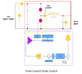
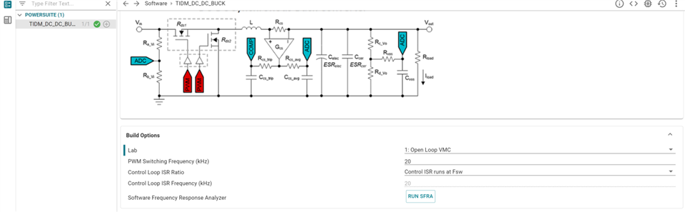
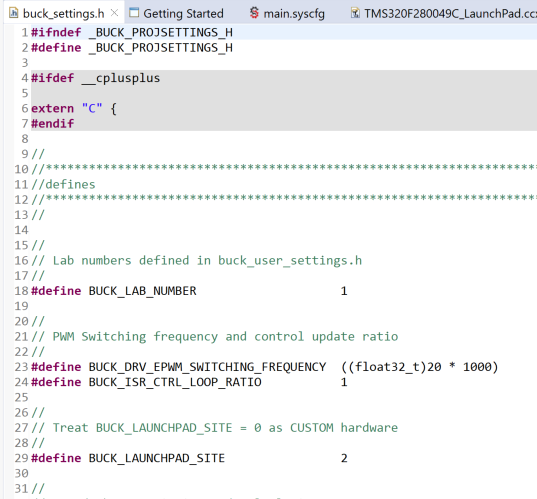
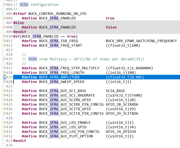
I am working on a buck converter and following the TIDM-DC-DC-BUCK firmware. While running SFRA with my 20kHz hardware setup, I observed a difference in the open-loop response in the SFRA GUI. I want to understand the discrepancy between the SFRA plot generated for the TIDM-DC-DC-BUCK kit, as shown on page 28 of the reference design user document, and the plot I obtained with my different power/voltage buck hardware at 20kHz. I have configured the TIDM-DC-DC-BUCK firmware according to the 20kHz switching frequency. According to the reference design document, the open-loop plot starts from a positive dB value, but in case of my power/voltage level hardware, it starts with a negative dB value, which conflicts with the expected buck converter open-loop response. Could you please shed some light on the missing link? If you need further information for your analysis, please let me know.
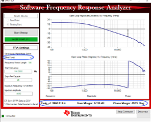
Open Loop SFRA plot for TIDM-DC-DC-BUCK-KIT (From reference manual page no. 28)
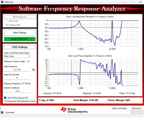
Open loop SFRA plot for my different power/voltage HW
Thanks & Regards,
Prathamesh Jadhav
Hi Prathamesh,
Can you explain about the hardware setup you are running on? For your custom hardware, how does it differ from the BOOSTXL-BUCKCONV hardware? Is it similar but you have changed some hardware component values? Be sure to update the values accordingly in the powerSUITE file or the settings.h file. You have migrated the code from F280049C to F280039C device? Note the increase CPU frequency on the F280039C device? Have you done any tuning on the control coefficients?
Regards,
Peter
Hi Peter,
Thanks for your response. Following are response to your questions:
a. We have a simple buck converter configuration with input voltage at 600 V and output voltage at 400 V. We have modified the HW components according to the mentioned ratings.
b. We have updated the switching frequency, voltage and current ratings in setting.h files accordingly.
c. Yes, we migrated code from 49C to 39C and have incorporated increased CPU frequency in the user setting files.
d. We want to perform tuning of control parameters. Hence, we first want to understand the open-loop response of the HW through SFRA.
Thanks & Regards,
Prathamesh
Hi Prathamesh,
Can you provide a high level block diagram of your design?
For your converter, when testing the buck performance, is everything operating as expected? Can you provide some scope shots of the Vin and Vout for reference to ensure the design is sound.
It would be good to double-check all changes made in the buck converter code to ensure that all changes are accounted for and correctly made conforming to your new design.
Regards,
Peter
Hi Peter,
Thank you for your reply.
a. I am adding high level block diagram of design below:
b. The buck converter performed as expected during testing.
c. Sharing with you the converter scope shots for Vin, Vnode, IL and Vout.
Thanks & Regards,
Prathamesh.
Hi Prathamesh,
Your provided scope shot seems to show correct buck performance for your system. Let me consult with some other experts to understand why you may be seeing differences in the SFRA behavior for your system
Regards,
Peter