Part Number: TMDSCNCD280049C
Other Parts Discussed in Thread: C2000WARE
Tool/software:
Hi Joselito,
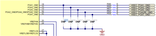
I have followed the recommendations provided in the 4.5 Evaluation of the Internal DC/DC Converter, but there appears to be some confusion regarding the PGA-GND configuration resistors. According to the Hardware References on page 12/21 (link: www.ti.com/.../spruic4d.pdf, resistors R55-R59 should be populated as they serve as the PGA-GND configurations in the context of an internal DC/DC converter. However, what about R7, R17, R21, R22, and R28? The MCU009B(001)_BOM specifies that these designators should remain unpopulated since the system was operating in VREG mode. Additionally, I am seeking clarification on the roles of R12:A and R13:A in the schematic when utilizing the internal DC/DC converter. Could you provide some insight into this? After implementing these changes, can the TMDSCNCD280049C still function in VREG mode through code configuration, or will it be restricted to operating solely in DC/DC converter mode? Does it have the capability to automatically switch between VREG and internal DC/DC converter mode?
Regards,
Reagan Ronald Colin Cooper
Coperlom Industries Engineering Service