Part Number: TMS320F280049C
Other Parts Discussed in Thread: LAUNCHXL-F280049C, DRV8161EVM, DRV8161, C2000WARE
Tool/software:
Hello,
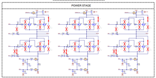
I am using the LAUNCHXL-F280049C with the 100 pin F280049CPZS. I am trying to get a BLDC motor to spin using the launchpad and 3x DRV816x motor drivers. I have built a PCB that is similar to the DRV816x EVM and have jumped the following signals from the launchpad to the motor driver board. The motor driver board takes PVDD (24V 1A), GVDD (12V 1A), 5Vin (5V 1A), as well as 3.3V from the launchpad.
| MCU Pin Number | MCU Signal (GPIO / ADC / Power) |
Motor Driver Signal
|
| 1 | 3.3V |
3.3V (Logic Power)
|
| 2 | PGA1/3/5_GND | CSAREF_C |
| 4 | GPIO40 | HALL_C |
| 6 | ADCINB3/VDAC | CSAREF_B |
| 8 | ADCIN4 | CSAREF_C |
| 11 | GPIO59 | nFAULT_C |
| 12 | GPIO23 | nFAULT_B |
| 13 | GPIO39 | nFAULT_A |
| 22 | GND | GND |
| 23 | ADCINA5 | VSEN_A |
| 24 | ADCINB0 | VSEN_B |
| 25 | ADCINC2 | VSEN_C |
| 26 | ADCINB1 | SEN_PVDD |
| 27 | ADCINB2 | ISEN_C |
| 28 | ADCINC0 | ISEN_B |
| 29 | ADCINA9 | ISEN_A |
| 30 | ADCINA1 | CSAREF_A |
| 33 | GPIO30 | HALL_B |
| 34 | GPIO58 | HALL_A |
| 35 | GPIO5 | INL_C (PWM3B) |
| 36 | GPIO4 |
INH_C (PWM3A)
|
| 37 | GPIO9 | INL_B (PWM5B) |
| 38 | GPIO8 |
INH_B (PWM5A)
|
| 39 | GPIO11 | INL_A (PWM6B) |
| 40 | GPIO10 |
INH_A (PWM6A)
|
Using the launchpad and motor driver board I have been able to get this motor to spin using the DRV8161EVM GUI (https://dev.ti.com/gallery/view/InternalBLDC/DRV8161-EVM-GUI/ver/0.1.4/). However, now I am trying to build a program within CCS to flash onto the C2000 that will give me motor motion without the use of the GUI. Simply, I just want to spin the motor after compiling on CCS. Is there some code available or could I get some assistance in writing a simple program on CCS to perform this task. I have already looked at the DRV8161_Sensored_Trapizoidal_GUI.c and DRV8161_Sensored_Trapizoidal_6x_PWM.c for help. These programs are complex and I have had no progress trying to replicate them.
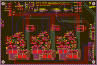
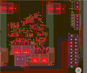
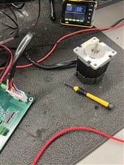
This is what my setup looks like. Launchpad (red), PCB board with 3x motor driver (green), Teknic motor (https://teknic.com/hudson-model/M-2311P-QN-08D/)
This is some code I have written for the launchpad that was flashed on CCS:
#include "driverlib.h"
#include "device.h"
//
// Constants
//
#define SYSCLK 100000000UL // 100 MHz system clock
#define PWM_FREQ 20000UL // 20 kHz PWM frequency
#define TBPRD (SYSCLK / (PWM_FREQ * 2)) // Timer period for up-down counter
//
// Pin definitions
//
#define PWM6A_GPIO 10 // GPIO10 (Pin 40)
#define PWM6B_GPIO 11 // GPIO11 (Pin 39)
#define PWM5A_GPIO 8 // GPIO8 (Pin 38)
#define PWM5B_GPIO 9 // GPIO9 (Pin 37)
#define PWM3A_GPIO 4 // GPIO4 (Pin 36)
#define PWM3B_GPIO 5 // GPIO5 (Pin 35)
//
// Function Prototypes
//
void initEPWMModules(void);
void initGPIOPins(void);
void setDutyCycle(uint16_t epwmBase, uint16_t dutyPercent);
void main(void)
{
//
// Initialize the device and GPIO
//
Device_init();
Device_initGPIO();
//
// Initialize GPIO pins for PWM
//
initGPIOPins();
//
// Initialize ePWM modules
//
initEPWMModules();
//
// Main loop: adjust duty cycle to 3% for all phases
//
while (1)
{
setDutyCycle(EPWM6_BASE, 3); // Phase A
setDutyCycle(EPWM5_BASE, 3); // Phase B
setDutyCycle(EPWM3_BASE, 3); // Phase C
DEVICE_DELAY_US(1000000); // 1 second delay
}
}
//
// Configure GPIO pins for PWM outputs
//
void initGPIOPins(void)
{
EALLOW;
// Configure GPIO for PWM outputs
GPIO_setPinConfig(GPIO_10_EPWM6A); // PWM6A
GPIO_setPinConfig(GPIO_11_EPWM6B); // PWM6B
GPIO_setPinConfig(GPIO_8_EPWM5A); // PWM5A
GPIO_setPinConfig(GPIO_9_EPWM5B); // PWM5B
GPIO_setPinConfig(GPIO_4_EPWM3A); // PWM3A
GPIO_setPinConfig(GPIO_5_EPWM3B); // PWM3B
EDIS;
}
//
// Initialize ePWM modules for complementary outputs
//
void initEPWMModules(void)
{
//
// Configure ePWM6 (Phase A)
//
EPWM_setTimeBasePeriod(EPWM6_BASE, TBPRD);
EPWM_setTimeBaseCounterMode(EPWM6_BASE, EPWM_COUNTER_MODE_UP_DOWN);
EPWM_setClockPrescaler(EPWM6_BASE, EPWM_CLOCK_DIVIDER_1, EPWM_HSCLOCK_DIVIDER_1);
EPWM_setActionQualifierAction(EPWM6_BASE, EPWM_AQ_OUTPUT_A, EPWM_AQ_OUTPUT_HIGH, EPWM_AQ_OUTPUT_ON_TIMEBASE_ZERO);
EPWM_setActionQualifierAction(EPWM6_BASE, EPWM_AQ_OUTPUT_A, EPWM_AQ_OUTPUT_LOW, EPWM_AQ_OUTPUT_ON_TIMEBASE_UP_CMPA);
EPWM_setActionQualifierAction(EPWM6_BASE, EPWM_AQ_OUTPUT_B, EPWM_AQ_OUTPUT_LOW, EPWM_AQ_OUTPUT_ON_TIMEBASE_ZERO);
EPWM_setActionQualifierAction(EPWM6_BASE, EPWM_AQ_OUTPUT_B, EPWM_AQ_OUTPUT_HIGH, EPWM_AQ_OUTPUT_ON_TIMEBASE_UP_CMPA);
//
// Configure ePWM5 (Phase B)
//
EPWM_setTimeBasePeriod(EPWM5_BASE, TBPRD);
EPWM_setTimeBaseCounterMode(EPWM5_BASE, EPWM_COUNTER_MODE_UP_DOWN);
EPWM_setClockPrescaler(EPWM5_BASE, EPWM_CLOCK_DIVIDER_1, EPWM_HSCLOCK_DIVIDER_1);
EPWM_setActionQualifierAction(EPWM5_BASE, EPWM_AQ_OUTPUT_A, EPWM_AQ_OUTPUT_HIGH, EPWM_AQ_OUTPUT_ON_TIMEBASE_ZERO);
EPWM_setActionQualifierAction(EPWM5_BASE, EPWM_AQ_OUTPUT_A, EPWM_AQ_OUTPUT_LOW, EPWM_AQ_OUTPUT_ON_TIMEBASE_UP_CMPA);
EPWM_setActionQualifierAction(EPWM5_BASE, EPWM_AQ_OUTPUT_B, EPWM_AQ_OUTPUT_LOW, EPWM_AQ_OUTPUT_ON_TIMEBASE_ZERO);
EPWM_setActionQualifierAction(EPWM5_BASE, EPWM_AQ_OUTPUT_B, EPWM_AQ_OUTPUT_HIGH, EPWM_AQ_OUTPUT_ON_TIMEBASE_UP_CMPA);
//
// Configure ePWM3 (Phase C)
//
EPWM_setTimeBasePeriod(EPWM3_BASE, TBPRD);
EPWM_setTimeBaseCounterMode(EPWM3_BASE, EPWM_COUNTER_MODE_UP_DOWN);
EPWM_setClockPrescaler(EPWM3_BASE, EPWM_CLOCK_DIVIDER_1, EPWM_HSCLOCK_DIVIDER_1);
EPWM_setActionQualifierAction(EPWM3_BASE, EPWM_AQ_OUTPUT_A, EPWM_AQ_OUTPUT_HIGH, EPWM_AQ_OUTPUT_ON_TIMEBASE_ZERO);
EPWM_setActionQualifierAction(EPWM3_BASE, EPWM_AQ_OUTPUT_A, EPWM_AQ_OUTPUT_LOW, EPWM_AQ_OUTPUT_ON_TIMEBASE_UP_CMPA);
EPWM_setActionQualifierAction(EPWM3_BASE, EPWM_AQ_OUTPUT_B, EPWM_AQ_OUTPUT_LOW, EPWM_AQ_OUTPUT_ON_TIMEBASE_ZERO);
EPWM_setActionQualifierAction(EPWM3_BASE, EPWM_AQ_OUTPUT_B, EPWM_AQ_OUTPUT_HIGH, EPWM_AQ_OUTPUT_ON_TIMEBASE_UP_CMPA);
}
//
// Set the duty cycle for the ePWM module
//
void setDutyCycle(uint16_t epwmBase, uint16_t dutyPercent)
{
uint16_t compareValue = (TBPRD * dutyPercent) / 100;
EPWM_setCounterCompareValue(epwmBase, EPWM_COUNTER_COMPARE_A, compareValue);
EPWM_setCounterCompareValue(epwmBase, EPWM_COUNTER_COMPARE_B, compareValue);
}
/////////////////////////////////////////////////////////////////////////////////////////////////////////////////////////////////////////////////////////////////////////////////////////////////////////////////////////////////////////////////////////////////////////////////
When this code is ran on CCS, these are the resulting waveforms for PWM6A, PWM6B as well as the power pulled from the different supplies.
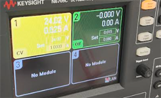
If I let this ccs code run longer, the mosfets begin to heat up but when GUI code is ran, the 24V supplies pulls around 0.3A.
EPWM6A waveform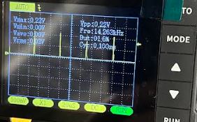
EPWM6B waveform
For reference, this is how the waveforms look when using the DRV816 EVM, the waveform also toggles on and off.
PWM6A
PWM6B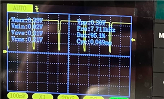
Thank you.