This thread has been locked.

If you have a related question, please click the "Ask a related question" button in the top right corner. The newly created question will be automatically linked to this question.

F29H85X-SOM-EVM: mcan_ex6_transmit_syscfg not working

Part Number: F29H85X-SOM-EVM
Other Parts Discussed in Thread: TMDSHSECDOCK, SYSCONFIG

Tool/software:

Hello everyone,

First of all, this is the hardware I'm using:

  • F29H85X-SOM-EVM MCU114E1-002
  • MCU134A Adapter
  • XDS110 Debugger
  • TMDSHSECDOCK rev F
  • NCV7351 CANFD Transceiver

So now with that background I can tell you I change on the sysconfig to match the HSEC pins 80 and 82, and I did connect those ones to TX and RX pins from transiever.

/**
 * These arguments were used when this file was generated. They will be automatically applied on subsequent loads
 * via the GUI or CLI. Run CLI with '--help' for additional information on how to override these arguments.
 * @cliArgs --device "F29H85x" --part "F29H85x_256ZEX" --package "256ZEX" --context "CPU1" --product "MCU_SDK_F29H85x@1.00.00.00"
 * @v2CliArgs --device "F29H850TU" --package "256ZEX" --variant "TMS320F29H850TU9" --context "CPU1" --product "MCU_SDK_F29H85x@1.00.00.00"
 * @versions {"tool":"1.22.0+3893"}
 */

/**
 * Import the modules used in this configuration.
 */
const clocktree = scripting.addModule("/driverlib/clocktree.js");
const jtag      = scripting.addModule("/driverlib/jtag.js");
const mcan      = scripting.addModule("/driverlib/mcan.js", {}, false);
const mcan1     = mcan.addInstance();

/**
 * Write custom configuration values to the imported modules.
 */
const divider8       = system.clockTree["MCANACLKDIV"];
divider8.divideValue = 10;

const divider15       = system.clockTree["PLL_REFDIV"];
divider15.divideValue = 1;

const multiplier1         = system.clockTree["PLL_IMULT"];
multiplier1.multiplyValue = 40;

const mux7       = system.clockTree["OSCCLKSRCSEL"];
mux7.inputSelect = "INTOSC2";


mcan1.$name                   = "myMCAN0";
mcan1.additionalCoreConfig    = true;
mcan1.stdFiltsUsed            = [0];
mcan1.loopbackMode            = false;
mcan1.nomRatePrescalar        = 0;
mcan1.nomTimeSeg1             = 9;
mcan1.nomTimeSeg2             = 8;
mcan1.nomSynchJumpWidth       = 8;
mcan1.dataRatePrescalar       = 0;
mcan1.mcan.$assign            = "MCAND";
mcan1.mcan.mcan_rxPin.$assign = "GPIO68";
mcan1.mcan.mcan_txPin.$assign = "GPIO67";
mcan1.periphClock.$name       = "driverlib_perClock0";
mcan1.periphConfig.$name      = "driverlib_perConfig0";
mcan1.stdFilt0.$name          = "stdFilt0";
mcan1.stdFilt0.sfec           = "MCAN_STDFILTEC_RXBUFF";
mcan1.stdFilt0.sfid1          = 4;

/**
 * Pinmux solution for unlocked pins/peripherals. This ensures that minor changes to the automatic solver in a future
 * version of the tool will not impact the pinmux you originally saw.  These lines can be completely deleted in order to
 * re-solve from scratch.
 */
jtag.JTAG.$suggestSolution        = "JTAG";
jtag.JTAG.tdoPin.$suggestSolution = "GPIO223/TDO";
jtag.JTAG.tdiPin.$suggestSolution = "GPIO222/TDI";

I know for a fact that the code is stock in this while:
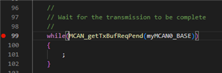
And this is because the MCAN_TXBRP is 2 so this means that the buffer is still pending to be sent.

I just want to double check that I'm not missing any other CAN related change on the hardware.

I would appreciate your support,

Martin

  • Hi Martin,

    A few questions to help get us started in debugging your issue.

    What is the goal of the project/application?

    Did you start from a specific mcan example and verify it works with the current HW (default on-board CAN transceiver)?

    Could you enable loopback mode in your current example and verify correct controller/buffer operation without influence of transceiver?

    How is the NCV7351connected to the MCAND TX/RX pins?

    Thanks for the additional information.

    Best Regards,

    Zackary Fleenor

  • Hello,

    Thanks for the answer to your questions:
    What is the goal of the project/application? 

    - I want to develop a CAN layer for the MCAN (we had it in other legacy projects with DCAN).

    Did you start from a specific MCAN example and verify it works with the current HW (default on-board CAN transceiver)?

    - Yes the loopback example ( mcan_ex6_transmit_syscfg ) works the problem is when I cancel that loopback.

    Could you enable loopback mode in your current example and verify correct controller/buffer operation without influence of transceiver?

    - Yes it worked as long is not without the loopback

    How is the NCV7351connected to the MCAND TX/RX pins?

    - Using the TMDSHSECDOCK rev F Pin 80 is RX and Pin 82 is TX

    Moreover in the example mcan_ex6_transmit_syscfg  I measure that up on the oscilloscope on the Tx and Rx.

    Tx is always high and Rx is always low.


    Thanks,

    Martin

  • Hey Martin,

    Thanks for this additional information. Can you confirm the HW resistor configuration for R25/R26/R27 and R29/R45/R54?

    These switches control whether GPIO67/68 are routed to CANTX/RX or GPIO64/65. The default configuration should be used in this case.

    Screenshot taken from https://www.ti.com/lit/df/sprm870b/sprm870b.pdf

    Best Regards,

    Zackary Fleenor

  • Hello Zackary,

    Earlier today, I did a small sample program to toggle both GPIO67 and CPIO68 and it worked.

    So I know then than those pins are routed to the output.

    Any other hardware or software related thing I can do to test this over?

    Thanks,

    Martin

  • Hello,

    Any updates?

    Thanks,

    Martin

  • Hello Martin,

    Glad to hear that you were able to verify the correct HW connectivity to these pins. Nothing obvious stands out from the current information.

    Can you provide the remainder of mcan_ex6_transmit_syscfg.c file and MCAN initialization code for additional review?

    Can you confirm GPIO67/68 mux mode configuration upon completion of the MCAN initialization?

    Best Regards,

    Zackary Fleenor

  • Hello Zackary,

    this is the code I'm using is the same one of the example just with some modifications to enable testing of the GPIOs:

    #include "board.h"
    #include "gpio.h"
    
    uint32_t counter = 0;
    
    void TogglePair() 
    {
      GPIO_togglePin(PINRX);
      GPIO_togglePin(PINTX);
    }
    
    //
    //  main function
    //
    
    int main(void) {
      MCAN_TxBufElement txMsg;
    
      //
      // Initialize device clock, peripheral clocks and interrupts
      //
      Device_init();
    
      //
      // Board initialization
      //
      Board_init();
    
      TogglePair();
    
      //
      // Initialize message to transmit.
      //
      txMsg.id = ((uint32_t)(0x4)) << 18U; // Identifier Value.
      txMsg.rtr = 0U;                      // Transmit data frame.
      txMsg.xtd = 0U;                      // 11-bit standard identifier.
      txMsg.esi = 0U;   // ESI bit in CAN FD format depends only on error
                        // passive flag.
      txMsg.dlc = 4U;   // CAN + CAN FD: transmit frame has 0-8 data bytes.
      txMsg.brs = 1U;   // CAN FD frames transmitted with bit rate
                        // switching.
      txMsg.fdf = 1U;   // Frame transmitted in CAN FD format.
      txMsg.efc = 1U;   // Store Tx events.
      txMsg.mm = 0xAAU; // Message Marker.
    
      //
      // Data bytes.
      //
      txMsg.data[0] = 0x12;
      txMsg.data[1] = 0x34;
      txMsg.data[2] = 0x56;
      txMsg.data[3] = 0x78;
    
      //
      // Write Tx Message to the Message RAM.
      //
      MCAN_writeMsgRam(myMCAN0_BASE, MCAN_MEM_TYPE_BUF, 1U, &txMsg);
    
      //
      // Add request for transmission.
      //
      MCAN_txBufAddReq(myMCAN0_BASE, 1U);
    
      //
      // Wait for the transmission to be complete
      //
      while (MCAN_getTxBufReqPend(myMCAN0_BASE)) 
      {
        if(counter > 200000)
        {
            TogglePair();
            counter = 0;
        }
        counter++;
      }
    
      //
      // Stop Application.
      //
      ESTOP0;
    }
    

    And this is the syscfg file:

    /**
     * These arguments were used when this file was generated. They will be automatically applied on subsequent loads
     * via the GUI or CLI. Run CLI with '--help' for additional information on how to override these arguments.
     * @cliArgs --device "F29H85x" --part "F29H85x_256ZEX" --package "256ZEX" --context "CPU1" --product "MCU_SDK_F29H85x@1.00.00.00"
     * @v2CliArgs --device "F29H850TU" --package "256ZEX" --variant "TMS320F29H850TU9" --context "CPU1" --product "MCU_SDK_F29H85x@1.00.00.00"
     * @versions {"tool":"1.22.0+3893"}
     */
    
    /**
     * Import the modules used in this configuration.
     */
    const clocktree = scripting.addModule("/driverlib/clocktree.js");
    const gpio      = scripting.addModule("/driverlib/gpio.js", {}, false);
    const gpio1     = gpio.addInstance();
    const gpio2     = gpio.addInstance();
    const jtag      = scripting.addModule("/driverlib/jtag.js");
    const mcan      = scripting.addModule("/driverlib/mcan.js", {}, false);
    const mcan1     = mcan.addInstance();
    
    /**
     * Write custom configuration values to the imported modules.
     */
    const divider8       = system.clockTree["MCANACLKDIV"];
    divider8.divideValue = 10;
    
    const divider15       = system.clockTree["PLL_REFDIV"];
    divider15.divideValue = 1;
    
    const multiplier1         = system.clockTree["PLL_IMULT"];
    multiplier1.multiplyValue = 40;
    
    const mux7       = system.clockTree["OSCCLKSRCSEL"];
    mux7.inputSelect = "INTOSC2";
    
    gpio1.$name             = "PINTX";
    gpio1.direction         = "GPIO_DIR_MODE_OUT";
    gpio1.writeInitialValue = true;
    gpio1.initialValue      = 1;
    gpio1.gpioPin.$assign   = "GPIO23";
    
    gpio2.direction         = "GPIO_DIR_MODE_OUT";
    gpio2.writeInitialValue = true;
    gpio2.$name             = "PINRX";
    gpio2.gpioPin.$assign   = "GPIO9";
    
    
    mcan1.$name                   = "myMCAN0";
    mcan1.additionalCoreConfig    = true;
    mcan1.stdFiltsUsed            = [0];
    mcan1.loopbackMode            = false;
    mcan1.nomRatePrescalar        = 0;
    mcan1.nomTimeSeg1             = 9;
    mcan1.nomTimeSeg2             = 8;
    mcan1.nomSynchJumpWidth       = 8;
    mcan1.dataRatePrescalar       = 0;
    mcan1.mcan.$assign            = "MCAND";
    mcan1.mcan.mcan_rxPin.$assign = "GPIO68";
    mcan1.mcan.mcan_txPin.$assign = "GPIO67";
    mcan1.periphClock.$name       = "driverlib_perClock0";
    mcan1.periphConfig.$name      = "driverlib_perConfig0";
    mcan1.stdFilt0.$name          = "stdFilt0";
    mcan1.stdFilt0.sfec           = "MCAN_STDFILTEC_RXBUFF";
    mcan1.stdFilt0.sfid1          = 4;
    
    /**
     * Pinmux solution for unlocked pins/peripherals. This ensures that minor changes to the automatic solver in a future
     * version of the tool will not impact the pinmux you originally saw.  These lines can be completely deleted in order to
     * re-solve from scratch.
     */
    jtag.JTAG.$suggestSolution        = "JTAG";
    jtag.JTAG.tdoPin.$suggestSolution = "GPIO223/TDO";
    jtag.JTAG.tdiPin.$suggestSolution = "GPIO222/TDI";
    

    This is the Mux configuration:

    Thanks,

    Martin

  • Hello, 

    Just to finish up this thread, A couple of days ago, I found out a jumper connector loose on my transceiver breakout board and also it seems that from TI side the documentation of the example is wrong, since the example says that the bit rates are 1000 mbps and 2000 mbps (and they are really 500 and 1000).

    After changing the jumper connection and correcting the Baud Rates on my CANoe simulation to the real bit rates, now the example is working.

    I would suggest TI to either correct the documentation or change the syscfg file to match the documentation.

    Thanks,

    Martin