This thread has been locked.

If you have a related question, please click the "Ask a related question" button in the top right corner. The newly created question will be automatically linked to this question.

TMS320F28P659SH-Q1: Issue in CAN Communication while Migrating from F28P65X Launchpad

Part Number: TMS320F28P659SH-Q1
Other Parts Discussed in Thread: SYSCONFIG, TCAN1043

Tool/software:

Hi,

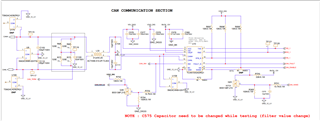
      I'm working in a project where I need to establish a CAN communication. I have a sample project which is working in my C2000 F28P65x launchpad but not working in my custom board. In my custom board it has F28P659SH6 PTP MCU. I'm using Sysconfig for migration and changing the pinmux for my custom board. I've also created a target config file and set build configuration as CPU1_RAM.

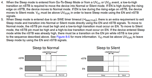
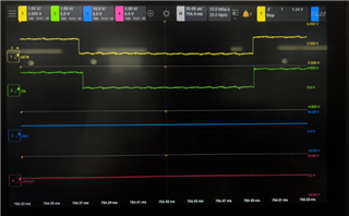
     I'm using TI's CAN transceiver IC [ TCAN1043ADRQ1 ] and set it to normal mode by setting nSTB = EN = High.

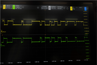
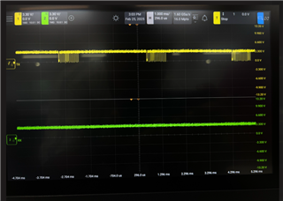
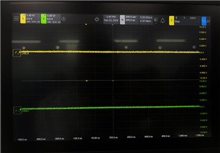
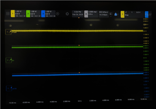
      I've checked the CAN error status register [CAN_ES] and CAN Error Counter register [CAN_ERRC]. I've attached the screenshot of those register for reference.

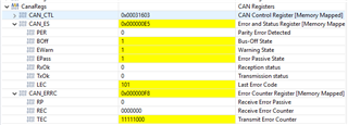
    Please let me know is that anything I'm missed out during migration and to how to solve this issue. Thanks in advance

  • Hello Subhash,

    Apologies for the delayed response while I was OOO last week.

    Can you provide more details on your test setup?

    How were you able to confirm working example with the Launchpad?

    Can you also probe both the TX/RX and CAN_H/CAN_L lines on your custom HW and provide screenshots?

    Best Regards,

    Zackary Fleenor

  • Hello Fleenor,

            My Test setup consists of C2000: F28P659SH6 PTP MCU where GPIO 70 and GPIO 71 is connected to Tx and RX pin of TCAN1043ADRQ1 CAN transceiver IC. I've attached the requested screenshots. PFA.

    Launch Pad : CAN_H and CAN_L

    Custom Board:

    1. Tx and Rx:


    2. CAN_H and CAN_L:

    Please let me know if anything else is required from my end.

    Thanks,

    Subhash

  • Hello Subhash,

    Thank you for providing these screenshots. Based on this information, it seems that the MCU is correctly configured to provide the correct CAN TX signal, but there appears to be an issue with the CAN Transceiver implementation since this isn't being reflected on the CAN_H/CAN_L terminals.

    Can you provide schematic of the TCAN1043A configuration?

    After quickly reviewing the associated Datasheet I have the following questions:

    1) Can you confirm the state of the nFault pin during this operation?

    2) Do you have the WAKE pin pulled permanently high or low to prevent unwanted LWU request?

    3) What is config for EN and nSTB pins?

    Best Regards,

    Zackary Fleenor

  • Hi Fleenor,

        Please find the answers below.

    1) Can you confirm the state of the nFault pin during this operation?

        Ans: nFault pin state was in Low state. Attached the scope shots below.

    2) Do you have the WAKE pin pulled permanently high or low to prevent unwanted LWU request?

        Ans: Wake pin is pulled Low. Schematic is attached for verification. Wake pin is configured as GPIO output in MCU and set it to output Low.

    3) What is config for EN and nSTB pins?

        Ans: En and nSTB are configured a GPIO output in MCU and set both of them to output High. Scope shot and schematics are attached for verification.

    CAN Schematic:

    Scope Shots of nFault, EN and nSTB:

    Thanks,

    Subhash

  • Hey Subash,

    Can you expand the Transceiver schematic shot to also show INH, VIO, and VCC connections?

    Based on the information so far, it seems that the issue isn't with the MCU device but likely with the transceiver.

    Can you also provide scope shots of the WAKE signal?

    I am going to reassign this thread to get a TCAN1043 Apps expert to review as well.

    Best Regards,

    Zackary Fleenor

  • Fleenor,

    Thanks for the help thus far.

    Subhash,

    It looks like your device may be in Sleep mode. As Fleenor suggested, can you please send over waveforms of INH, along with nSTB, EN, VCC, and VIO? 

    Regards,

    Eric Hackett 

  • Hi Eric,

    I have attached the scope shots of INH, VCC and VIO waveforms below. The waveforms of EN, nSTBN and nFault behaves same, those waveforms were attached in previous response.

    Please have a look and let me know if anything is required from my end.

    Schematic:

  • Hi Fleenor,

    Thanks for the help, I've attached the full schematic of CAN in below response. I'm getting 0V from the wake signal.

    Thanks,

    Subhash

  • Hi Subhash, 

    Thanks for sharing that new waveform. 

    Because INH is low, this points to the fact that TCAN1043A is in Sleep mode as Eric mentioned. To enter Normal mode from Sleep mode, EN must be high and a low-to-high transition on nSTB is needed. I recommend looking at Figure 8-4 in the datasheet and the paragraphs below it (4 and 5):

    Also please ensure you are using the correct datasheet for TCAN1043A. The other versions have different methods of exiting sleep mode. Once INH, EN, nSTB are all high, then this signifies that TCAN1043A is in Normal mode where TX can transmit to the bus.

    Best,

    Ethan

  • Hi Ethan,

    I have attached the waveform of INH and TX pins, after making INH pin high the TX pin also became high. Previously when the INH was in Low state, I can be able to see waveforms in TX pin [waveforms attached in above response]. Please refer the waveform below.

    I've made sure that INH,nSTB and EN pins are all high and I'm referring the TCAN1043datasheet as well.

    Thanks,

    Subhash

  • Hi Subhash,

    Are you still not able to communicate on the bus?

    TXD is a logic input and is not connected to INH. 

    If INH, nSTB, and EN are all high and you still cannot communicate on the bus with TXD, then you are likely in Silent mode which has the driver disabled. This is due to the TXD Clamp flag (Section 8.3.7.1.5. of the datasheet). If TXD is low while entering Normal mode, TCAN1043A will enter Silent mode. In this case, ensure TXD is high and add a delay (1ms will work) before transmitting to TXD. This will allow the device to fully enter Normal mode without triggering TXDCLP.

    Let me know if that fixed the issue,

    Ethan

  • Hi Ethan,

    Even after giving delay before transmitting and still can't be able to transmit data. 

    1. During power on the EN, nSTB and INH became High then I move it to debug mode and when I run both EN and nSTB pins became low. At first EN became low and after 2.3us the nSTB became low.

    2. After completing the initializations I'm again making the EN and nSTB pins High. It takes around 40us to complete the Initialization process and then make nSTB pin high then after 20us I'm making EN pin High.

    3. All these times the INH pin status was HIGH.

    4. The RXD and nFault pin are Low.

    5. By any chance does this sequence affects the modes. I feel that it doesn't goes to normal mode.

    If possible, can we sync up in a call and sort this issue it will be really helpful.

    Thanks,

    Subhash

  • Hi Subhash,

    Please share a waveform with EN, nSTB, INH, and nFAULT all together when trying to enter Normal mode. This is the best way for me to help troubleshoot this issue. 

    1. During power on the EN, nSTB and INH became High then I move it to debug mode and when I run both EN and nSTB pins became low. At first EN became low and after 2.3us the nSTB became low.

    I am not familiar with debug mode, but EN and nSTB going low is due to the controller configuration. I would check to see if the nFAULT state has anything to do with EN and nSTB going low from the controller side.  

    2. After completing the initializations I'm again making the EN and nSTB pins High. It takes around 40us to complete the Initialization process and then make nSTB pin high then after 20us I'm making EN pin High.

    If the device was previously in Standby mode (EN=low, nSTB=low, INH=high), then TCAN1043A should be in Normal mode. So your approach here is correct.

    4. The RXD and nFault pin are Low.

    However, nFAULT being low might be a helpful indication. There are multiple reasons why nFAULT can be low (Table 8-1 in the datasheet explains this). Particularly the "Local Faults" part of the table explains that the device will enter Silent mode under the right conditions. This mode has the driver disabled which could explain why you cannot communicate. 

    After I have reviewed the additional requested waveforms and we cannot determine the root issue, we can certainly setup a call. 

    Best,

    Ethan

  • Hi Ethan,

          I've attached the waveform image of nSTB, EN, INH, nFault below for your reference. It's captured during startup process. Please let me know if anything else is needed.

    Thanks,

    Subhash

  • Hi Subhash,

    Can you clarify what you mean by startup process? Do you mean when VSUP is turned on to a valid level?

    From that waveform, we can see that nFAULT is low. This indicates that there is a fault somewhere in the system which is preventing transmission. There are a variety of nFAULT=low sources so please review Table 8-1 in the datasheet for the cause.  

    If you could show additional waveforms with EN, nSTB while adding TX/RX, and another waveform with EN, nSTB, CANH/CANL that would be helpful.

    Best,

    Ethan