Part Number: TMDSCNCD28379D
Other Parts Discussed in Thread: SYSCONFIG, TMS320F28379D, , C2000WARE
Tool/software:
Hi,
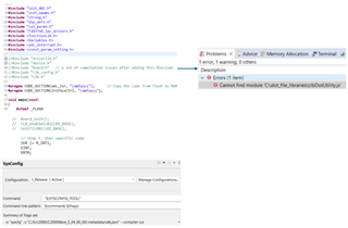
I am trying to use CLB tool to do a very simple logics but it is hard for me. Could you please help me?
I have 5 signals from 5 GPIOs, say GPIO1, GPIO2, GPIO3, GPIO4, GPIO5.and I am trying to use CLB to make them ORed to one GPIO, say GPIO6. From sysConfig, I found 5 items related to CLB but don’t know how they connect each other.
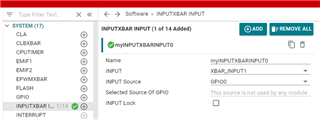
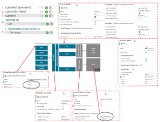
Step1: Input GPIOs configuration under CLB INPUTXBAR INPUT
1.1: Number of CLB INPUTXBAR INPUT = Number of input GPIOs?
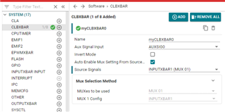
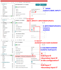
Step2: signals configuration under CLBXBAR
2.1: Number OF CLBXBAR = Number of GPIOs?
2.2: Selection of Aux Signal input: one from 8 AUXSIGx, which one should I choose. It looks like it is CLB output shown in the CLB X-BAR Architecture. Here is the name for the signal input. What does this signal connect, one of the input GPIOs in my case? Where to confirm the connections?
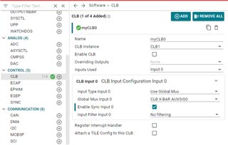
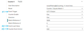
Step3: Tile Design under CLB
3.1: what do I need to choose for i0, i1, i2, i3? They should be signals from GPIOs.
3.2: I have 5 signals from 5 GPIOs to be processed. Can I only have 1 CLB since each CLB has three 4-input-LUTs?
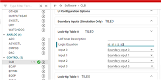
LUT0 equation: i0 | i1| i2 | i3 = LUT 0 Output. i0 is from GPIO0, i1 is from GPIO1, i2 is from GPIO2, i3 is from GPIO3.
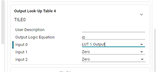
LUT1 equation: i0 | I1 | i2 = LUT 1 Output. i0 is from GPIO4, i1 is from GPIO5, i2 is from LUT 0 Output.
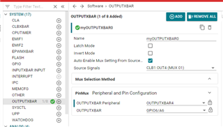
Step4: Output GPIOs configuration under CLB OUTPUTXBAR
4.1: Number of CLB OUTPUTXBAR = Number of output GPIOs?
4.2: How to confirm that LUT 1 output is connected to the specified output GPIO, say GPIO6 in my case?
Thanks,
Hongmei Wan