This thread has been locked.

If you have a related question, please click the "Ask a related question" button in the top right corner. The newly created question will be automatically linked to this question.

TMS320F2800135: How to measure DC current of the Inverter with less error?

Part Number: TMS320F2800135


Tool/software:

Hi,

We are trying to measure the DC current of an inverter with the help of low side current shunt. 

Observation:

Error is less than 5% in the DC current from sensed value to clamp meter value. (Running an AC motor with V/f control having PF >0.5)

Error is almost 50% in the DC current from sensed value to clamp meter value. (Running an AC motor with V/f control having PF <0.4)

Verified: There is no problem with the motor or scaling of the controller in DC sensing. As, proper value being sensed with PF>0.5 motors and or motor under condition also measuring proper DC current.

is there any effect of PF of the AC motor in DC current sensing? How to achieve proper DC current sensing for all motors?

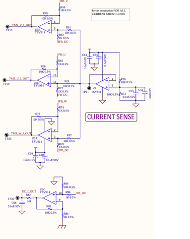
The following OPAMP circuitry has been used in the Hardware sensing.

Thanks & Regards

  • Hello,

    Apologies for the delayed response as the original owner for this query is unavailable. I am looking into your query now.

    To address your first question:

    Effect of Power Factor on DC Current Sensing:

    1. High PF (>0.5):
    - Current and voltage are more in phase
    - More real power consumption
    - DC bus current is more stable
    - Less ripple content
    - More accurate sensing possible

    2. Low PF (<0.4):
    - Large phase difference between voltage and current
    - Higher reactive power component
    - Creates larger ripple in DC bus current
    - Instantaneous current varies significantly
    - Traditional averaging methods fail

    In regard to your second question:

    The following best practices are recommended for the best performance of the DC Motor Current Senor circuitry:

    1. Use synchronized sampling with PWM
    2. Implement proper filtering
    3. Consider both hardware and software solutions (Oversampling/Averaging, SW/HW Filtering)
    4. Calibrate system with different PF loads
    5. Monitor temperature effects on sensing
    6. Regular auto-calibration routines

    Hardware Recommendations:
    - Use high-bandwidth current sensors
    - Proper anti-aliasing filters
    - Place sensor close to DC bus capacitors
    - Consider isolated current sensors

    Please keep these in consideration during your design.

    The screenshots your provided of the HW implementation are not very legible, is it possible to provide a higher resolution version of the schematic?

    Best Regards,

    Zackary Fleenor