Other Parts Discussed in Thread: C2000WARE
Tool/software:
Hello All,
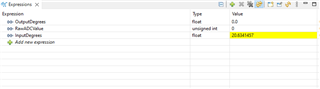
I have the following code that runs some servos and read the feedback using ADC. I am unable get the updated RawADC values in the debug session. But this problem does not occur in the older version CCS Studio 9 (C2000 Ware 4_03). So what changes need to be made to make it amenable to current version.
Here is the standalone code that runs the motors and read the ADC feedback.
#include "F28x_Project.h"
#define PCA1_SLAVE_ADDR 0x41 // First PCA9685 I2C Address
#define PCA2_SLAVE_ADDR 0x40 // Second PCA9685 I2C Address
#define MODE1_REG 0x00 // MODE1 register address
#define PRESCALE_REG 0xFE // PRESCALE register address (for PWM frequency)
#define LED0_ON_L 0x06 // First channel ON low byte
#define LED0_OFF_L 0x08 // First channel OFF low byte
// Constants
#define pulse_min 102.0f // 0.5 ms in counts
#define pulse_max 512.0f // 2.5 ms in counts
#define DEGREE_MIN 0.0f // Minimum servo angle
#define DEGREE_MAX 180.0f // Maximum servo angle
#define ADC_MAX_COUNTS 4095.0f // 12-bit ADC maximum value
#define ADC_REF_VOLTAGE 3.3f // Reference voltage of the ADC
// Calibration values for servo feedback, measured at mechanical endpoints:
//static const uint16_t adcMin = 700; // Raw ADC count at servo's minimum position
//static const uint16_t adcMax = 2500; // Raw ADC count at servo's maximum position
// Global Variables
Uint16 PWM_Frequency = 50; // Set default PWM frequency (in Hz)
Uint16 PWM_PulseWidth[20]; // Array to store pulse widths for 20 servos
Uint16 pulse_increment = 1; // Increment for adjusting PWM width
Uint16 time_index = 0;
float InputDegrees = 0.0f; // Degrees sent to Servo 20 (global variable for CCS)
float OutputDegrees = 0.0f; // Degrees sensed from Servo 20 feedback (via ADC)
Uint16 RawADCValue = 0; // Raw ADC value for debugging
float SensedPulseWidth = 0.0f; // Calculated pulse width from ADC
// ------------------------------------------------------------------------------
// Externally Adjustable Variables (Watch/we can Change in CCS)
// ------------------------------------------------------------------------------
float adcMin = 650.0f; // Raw ADC value at servo's mechanical min angle(645 is working fine)
float adcMax = 2500.0f; // Raw ADC value at servo's mechanical max angle
float pulseMin = 102.0f; // Pulse-width counts at servo min (e.g., ~0.5 ms)(these settings are specifically meant for 50 Hz)
float pulseMax = 512.0f; // Pulse-width counts at servo max (e.g., ~2.5 ms)
// We can tune these four in CCS watch window to match our system
// Function Prototypes
void I2C_Init(void);
void I2C_Write(Uint16 slave_addr, Uint16 reg, Uint16 data, Uint16 count);
void Set_Servo_PWM(Uint16 servo_num, Uint16 on_time, Uint16 off_time);
void PCA9685_Init(void);
void InitI2CGpio(void);
// --- ADC-Related Prototypes ---
void ADC_Init(void);
static void ADC_PinMuxConfig(void);
Uint16 Read_ADC(void);
float Convert_PWM_To_Degrees(float pulse_width);
void Update_OutputDegrees(void);
int main(void)
{
Uint16 servo_num, on_time, off_time;
// Uint16 pulse_min = 102; // 0.5ms for 50Hz PWM (on-time value)clock wise
// Uint16 pulse_min = 450; // 0.5ms for 50Hz PWM (on-time value)
// Uint16 pulse_max = 512; // 2.5ms for 50Hz PWM (off-time value)
// Uint16 pulse_max = 512; // 1.5ms for 50Hz PWM (off-time value)anti clockwise
// Initialize system control, GPIO, and I2C module
InitSysCtrl();
InitI2CGpio();
I2C_Init();
// Configure the pin for ADC-D1
ADC_PinMuxConfig();
// Initialize the ADC
ADC_Init();
// Initialize both PCA9685 devices (set frequency to 50Hz)
PCA9685_Init();
// Initialize pulse width for each servo at the minimum value (0.5ms)
for (servo_num = 0; servo_num < 20; servo_num++) {
PWM_PulseWidth[servo_num] = pulse_min;
}
// Main loop to continuously vary PWM signal for all 20 servos
while(1)
{
for (servo_num = 0; servo_num < 20; servo_num++) {
// Set ON time to 0 and OFF time to the current pulse width
on_time = 0;
off_time = PWM_PulseWidth[servo_num];
// Set PWM for the current servo
Set_Servo_PWM(servo_num, on_time, off_time);
// 3) If this is servo #20 (index 19), convert pulse width to degrees
// and store in an “InputDegrees” variable (for display or debugging).
if (servo_num == 19) // Servo #20
{
float servo20PulseWidth = PWM_PulseWidth[servo_num];
InputDegrees = Convert_PWM_To_Degrees(servo20PulseWidth);
// Now “InputDegrees” reflects the degrees commanded to servo #20
// Sample feedback for Servo 20 (via ADC-D1)
Update_OutputDegrees(); // This updates OutputDegrees using ADC feedback
}
// Adjust the pulse width for the next iteration
PWM_PulseWidth[servo_num] += pulse_increment;
// Reverse the increment if the pulse width goes out of bounds (between 0.5ms and 2.5ms)
if (PWM_PulseWidth[servo_num] > pulse_max || PWM_PulseWidth[servo_num] < pulse_min) {
pulse_increment = -pulse_increment;
}
}
// Add a delay to smooth out the PWM changes
DELAY_US(40000); // Delay of 10ms to simulate smooth servo movement
}
}
//------------------------------------------------------------------------------
// Function to convert PWM pulse width to degrees
//------------------------------------------------------------------------------
float Convert_PWM_To_Degrees(float pulse_width)
{
// Linear mapping from [pulse_min .. pulse_max] => [DEGREE_MIN .. DEGREE_MAX]
return DEGREE_MIN
+ ((pulse_width - pulse_min) / (pulse_max - pulse_min))
* (DEGREE_MAX - DEGREE_MIN);
}
//------------------------------------------------------------------------------
// ADC_PinMuxConfig - Configure the GPIO pin for ADC-D1
//------------------------------------------------------------------------------
static void ADC_PinMuxConfig(void)
{
// NOTE: Check the device-specific datasheet to ensure
// that GPIO30 corresponds to ADC-D1 on the package.
// For many F2837x devices, ADC-D1 can be on GPIO30.
// If our design has ADC-D1 on a different pin, modify accordingly.
EALLOW;
// Make sure the pin is configured as an analog input to the ADC:
// Typically for F2837xD:
GpioCtrlRegs.GPADIR.bit.GPIO30 = 0; // input
// Set MUX to 3 for ADC (check TRM/datasheet for correct setting)
GpioCtrlRegs.GPAMUX2.bit.GPIO30 = 3;
EDIS;
}
//------------------------------------------------------------------------------
// ADC_Init - Initialize ADC-D (12-bit, single-ended, Channel D1).
//------------------------------------------------------------------------------
void ADC_Init(void)
{
EALLOW;
// 1. Power up the ADC
// Set prescale => ADCCLK = SYSCLK / (1 + PRESCALE)
AdcdRegs.ADCCTL2.bit.PRESCALE = 6;
// 2. Set ADC mode to 12-bit resolution, single-ended
// (Pass in "ADCD" if our header defines ADC_ADCD for the module ID)
AdcSetMode(ADC_ADCD, ADC_RESOLUTION_12BIT, ADC_SIGNALMODE_SINGLE);
// 3. Set interrupt pulse at the end of conversion
AdcdRegs.ADCCTL1.bit.INTPULSEPOS = 1;
// 4. Enable ADC power
AdcdRegs.ADCCTL1.bit.ADCPWDNZ = 1;
EDIS;
// 5. Wait for ADC to power up (datasheet recommends ~1 ms)
DELAY_US(1000);
// 6. Configure SOC0
EALLOW;
// Channel Select: 1 => ADC-D1
AdcdRegs.ADCSOC0CTL.bit.CHSEL = 1;
// Sample window (ACQPS). Minimum: (resolution cycles) + overhead.
// For 12-bit, 75+ ns can suffice, 14 is a typical safe value.
AdcdRegs.ADCSOC0CTL.bit.ACQPS = 14;
// Trigger source: 5 = software trigger
AdcdRegs.ADCSOC0CTL.bit.TRIGSEL = 5;
// Select EOC0 to set INT1 flag
AdcdRegs.ADCINTSEL1N2.bit.INT1SEL = 0; // EOC0 => ADCINT1
AdcdRegs.ADCINTSEL1N2.bit.INT1E = 1; // Enable ADCINT1
// Clear any spurious interrupt flags
AdcdRegs.ADCINTFLGCLR.bit.ADCINT1 = 1;
EDIS;
}
//------------------------------------------------------------------------------
// Read_ADC - Software-trigger SOC0, wait for EOC, return ADC result
//------------------------------------------------------------------------------
Uint16 Read_ADC(void)
{
Uint16 timeout = 10000; // simple timeout to avoid endless loop
// 1. Force SOC0
EALLOW;
AdcdRegs.ADCSOCFRC1.all = 0x01; // Force SOC0
EDIS;
// 2. Wait until conversion completes or timeout
while((AdcdRegs.ADCINTFLG.bit.ADCINT1 == 0) && (timeout > 0))
{
timeout--;
}
// 3. Check for timeout
if(timeout == 0)
{
// Timeout: debug or handle error
RawADCValue = 0;
return 0;
}
// 4. Clear interrupt flag
AdcdRegs.ADCINTFLGCLR.bit.ADCINT1 = 1;
// 5. Read result
RawADCValue = AdcdResultRegs.ADCRESULT0;
return RawADCValue;
}
//------------------------------------------------------------------------------
// Update_OutputDegrees - Reads ADC and converts to "degrees"
//------------------------------------------------------------------------------
void Update_OutputDegrees(void)
{
// 1. Read the raw ADC value
RawADCValue = Read_ADC();
// 2) Convert raw ADC to a 0..1 normalized value based on servo's calibration
// (adcMin..adcMax are the servo's actual limits)
float scaledAdc = (RawADCValue - (float)adcMin) / (float)(adcMax - adcMin);
// 3) Clamp between 0..1 in case of minor overshoot or undershoot
if (scaledAdc < 0.0f) scaledAdc = 0.0f;
if (scaledAdc > 1.0f) scaledAdc = 1.0f;
// 4) Map the normalized value to the known pulse_min..pulse_max range
SensedPulseWidth = pulse_min + (scaledAdc * (pulse_max - pulse_min));
// 5) Finally, convert that pulse width to degrees
// e.g., 0.5 ms => 0°, 2.5 ms => 180° (or whatever your servo truly supports)
OutputDegrees = DEGREE_MIN
+ ((SensedPulseWidth - pulse_min) / (pulse_max - pulse_min))
* (DEGREE_MAX - DEGREE_MIN);
// Now OutputDegrees should closely reflect the servo’s actual angle
}
// Function to initialize I2C
void I2C_Init(void)
{
EALLOW;
I2caRegs.I2CMDR.all = 0x0000; // Reset I2C module
I2caRegs.I2CPSC.all = 6; // Prescaler for 200 MHz clock
I2caRegs.I2CCLKL = 145; // Low time for I2C clock (for 100 kHz)
I2caRegs.I2CCLKH = 145; // High time for I2C clock (for 100 kHz)
I2caRegs.I2CMDR.all = 0x0020; // Enable master mode
I2caRegs.I2CSTR.all = 0x0000; // Clear status register
EDIS;
}
// Function to write data to a register of the PCA9685
void I2C_Write(Uint16 slave_addr, Uint16 reg, Uint16 data, Uint16 count)
{
I2caRegs.I2CSAR.all = slave_addr; // Set slave address
I2caRegs.I2CMDR.all = 0x6E20; // Master transmit, start condition
I2caRegs.I2CCNT = count; // Set number of bytes to transmit
I2caRegs.I2CDXR.all = reg; // Register address to write to
DELAY_US(500);
// while (I2caRegs.I2CSTR.bit.ARDY == 0); // Wait until register address is sent
I2caRegs.I2CDXR.all = data; // Write the data to the register
DELAY_US(500);
// while (I2caRegs.I2CSTR.bit.ARDY == 0); // Wait until data is sent
}
// Function to set PWM for each servo
void Set_Servo_PWM(Uint16 servo_num, Uint16 on_time, Uint16 off_time)
{
Uint16 slave_addr = (servo_num < 10) ? PCA1_SLAVE_ADDR : PCA2_SLAVE_ADDR;
Uint16 channel = servo_num % 10; // Channel on the PCA device (0-9)
Uint16 on_low = (on_time & 0xFF); // Extract low byte of ON-time
Uint16 on_high = ((on_time >> 8) & 0x0F); // Extract high byte of ON-time
Uint16 off_low = (off_time & 0xFF); // Extract low byte of OFF-time
Uint16 off_high = ((off_time >> 8) & 0x0F); // Extract high byte of OFF-time
// Write ON time to the correct channel
I2C_Write(slave_addr, LED0_ON_L + 4 * channel, on_low, 2);
I2C_Write(slave_addr, LED0_ON_L + 1 + 4 * channel, on_high, 2);
// Write OFF time to the correct channel
I2C_Write(slave_addr, LED0_OFF_L + 4 * channel, off_low, 2);
I2C_Write(slave_addr, LED0_OFF_L + 1 + 4 * channel, off_high, 2);
}
// Function to initialize PCA9685 devices
void PCA9685_Init(void)
{
// Write to MODE1 register to reset both PCA devices
I2C_Write(PCA1_SLAVE_ADDR, MODE1_REG, 0x80, 2); // Reset PCA1
I2C_Write(PCA2_SLAVE_ADDR, MODE1_REG, 0x80, 2); // Reset PCA2
DELAY_US(10000); // Wait for 10 ms
// Write to MODE1 register to Sleep both PCA devices
I2C_Write(PCA1_SLAVE_ADDR, MODE1_REG, 0x10, 2); // Sleep PCA1
I2C_Write(PCA2_SLAVE_ADDR, MODE1_REG, 0x10, 2); // Sleep PCA2
DELAY_US(10000); // Wait for 10 ms
// Set PWM frequency (50Hz) by writing prescale register
I2C_Write(PCA1_SLAVE_ADDR, PRESCALE_REG, 0x79, 2); // Set 50Hz for PCA1
I2C_Write(PCA2_SLAVE_ADDR, PRESCALE_REG, 0x79, 2); // Set 50Hz for PCA2
DELAY_US(10000); // Wait for 10 ms
// Write to MODE1 register to wake up both PCA devices
I2C_Write(PCA1_SLAVE_ADDR, MODE1_REG, 0xA1, 2); // Wake up PCA1
I2C_Write(PCA2_SLAVE_ADDR, MODE1_REG, 0xA1, 2); // Wake up PCA2
DELAY_US(10000); // Wait for 10 ms
}
// Function to initialize I2C GPIOs
void InitI2CGpio(void)
{
EALLOW;
GpioCtrlRegs.GPBPUD.bit.GPIO32 = 0; // Enable pull-up on GPIO32 (SDAA)
GpioCtrlRegs.GPBPUD.bit.GPIO33 = 0; // Enable pull-up on GPIO33 (SCLA)
GpioCtrlRegs.GPBQSEL1.bit.GPIO32 = 3; // Asynchronous input GPIO32 (SDAA)
GpioCtrlRegs.GPBQSEL1.bit.GPIO33 = 3; // Asynchronous input GPIO33 (SCLA)
GpioCtrlRegs.GPBMUX1.bit.GPIO32 = 1; // Configure GPIO32 as SDAA
GpioCtrlRegs.GPBMUX1.bit.GPIO33 = 1; // Configure GPIO33 as SCLA
EDIS;
}