This thread has been locked.

If you have a related question, please click the "Ask a related question" button in the top right corner. The newly created question will be automatically linked to this question.

TMS320F28388S: PHERIPHRAL FREQENCY

Part Number: TMS320F28388S
Other Parts Discussed in Thread: C2000WARE

Tool/software:

I am using device library so i have only on options to Peripheral frequency ie (125 MHZ if OSC is 25MHZ)

but i need 180MHZ frequency 

can you please guide me to get 180MHZ

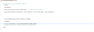
Please check code i have written but it is not working 

Provide me solution for this 

  • Hi Tejashri,

    XTAL operates at 20 MHz by default, so the IMULT needs to be modified to 18. You can use other combinations of multipliers and dividers as well. 

    Best Regards,

    Aishwarya

  • hello Aishwarya,

        can you please check and review my  code 

    #include "driverlib.h"
    #include "device.h"
    #include "board.h"

    //
    // Globals
    //
    uint16_t myADC0Result0;
    uint16_t myADC0Result1;
    uint16_t myADC1Result0;
    uint16_t myADC1Result1;

    //
    // Main
    //
    void main(void)
    {
    //
    // Initialize device clock and peripherals
    //
    Device_init();

    //
    // Disable pin locks and enable internal pullups.
    //
    Device_initGPIO();

    //
    // Initialize PIE and clear PIE registers. Disables CPU interrupts.
    //
    Interrupt_initModule();

    //
    // Initialize the PIE vector table with pointers to the shell Interrupt
    // Service Routines (ISR).
    //
    Interrupt_initVectorTable();

    Pin_Init();

    //
    // Set up ADCs, initializing the SOCs to be triggered by software
    // Signal Mode : single-ended
    // Conversion Resolution : 12-bit;
    //
    Board_init();

    //
    // Enable Global Interrupt (INTM) and realtime interrupt (DBGM)
    //
    EINT;
    ERTM;


    //initCPUTimersinit();

    configureSystemClock();

    // Loop indefinitely
    //
    while(1)
    {
    //
    // Convert, wait for completion, and store results
    //
    ADC_forceMultipleSOC(myADC0_BASE, (ADC_FORCE_SOC0 | ADC_FORCE_SOC1));

    //
    // Wait for ADCA to complete, then acknowledge flag
    //
    while(ADC_getInterruptStatus(myADC0_BASE, ADC_INT_NUMBER1) == false)
    {
    }
    ADC_clearInterruptStatus(myADC0_BASE, ADC_INT_NUMBER1);

    ADC_forceMultipleSOC(myADC1_BASE, (ADC_FORCE_SOC0 | ADC_FORCE_SOC1));
    //
    // Wait for ADCC to complete, then acknowledge flag
    //
    while(ADC_getInterruptStatus(myADC1_BASE, ADC_INT_NUMBER1) == false)
    {
    }
    ADC_clearInterruptStatus(myADC1_BASE, ADC_INT_NUMBER1);

    //
    // Store results
    //
    myADC0Result0 = ADC_readResult(ADCARESULT_BASE, ADC_SOC_NUMBER0);
    myADC0Result1 = ADC_readResult(ADCARESULT_BASE, ADC_SOC_NUMBER1);
    myADC1Result0 = ADC_readResult(ADCCRESULT_BASE, ADC_SOC_NUMBER0);
    myADC1Result1 = ADC_readResult(ADCCRESULT_BASE, ADC_SOC_NUMBER1);

    //
    // Software breakpoint. At this point, conversion results are stored in
    // myADC0Result0, myADC0Result1, myADC1Result0, and myADC1Result1.
    //
    // Hit run again to get updated conversions.
    //
    ESTOP0;
    }
    }

    void Pin_Init(void)
    {
    GPIO_setDirectionMode(31, GPIO_DIR_MODE_OUT);

    // Configure GPIO13 as a GPIO (not peripheral function)
    GPIO_setPinConfig(GPIO_31_GPIO31);

    //GPIO_writePin(13, 1);

    // Set output to LOW initially
    // GPIO_writePin(13, 0);

    // Optionally enable output qualification (default is sync mode)
    // GPIO_setQualificationMode(13, GPIO_QUAL_SYNC);


    }


    void configureSystemClock(void)
    {

    // Enable write access to protected registers
    EALLOW;

    unlockRegs();

    // Step 1: Set the oscillator source (XTAL or INTOSC)
    SysCtl_selectOscSource(SYSCTL_OSCSRC_XTAL); // Select external crystal

    SysCtl_setClock(SYSCTL_OSCSRC_XTAL | SYSCTL_IMULT(18) | SYSCTL_FMULT_NONE | SYSCTL_SYSDIV(2));
    // Step 3: Enable Peripheral Clocks (Example: Enable GPIO and TIMER clocks)
    //SysCtl_enablePeripheral(SYSCTL_PERIPH_CLK_GPIOA);
    SysCtl_enablePeripheral(SYSCTL_PERIPH_CLK_TIMER0);

    lockRegs();

    uint32_t sysClockFreq = SysCtl_getClock(DEVICE_OSCSRC_FREQ);
    // printf("System Clock Frequency: %lu Hz\n", sysClockFreq);


    EDIS;

    }


    void unlockRegs(void)
    {
    EALLOW;
    // Unlock protected registers
    HWREG(CLKCFG_BASE + SYSCTL_O_CLKSRCCTL1) = 0x0;
    HWREG(CLKCFG_BASE + SYSCTL_O_SYSPLLCTL1) = 0x0;
    EDIS;
    }


    void lockRegs(void)
    {
    EALLOW;
    // Lock the protected registers by setting the appropriate bits
    HWREG(CLKCFG_BASE + SYSCTL_O_CLKSRCCTL1) = 0x1; // Lock Clock Configuration
    HWREG(CLKCFG_BASE + SYSCTL_O_SYSPLLCTL1) = 0x1; // Lock PLL Configuration
    EDIS;
    }

    And where i will get unlock and lock resister API  and void configureSystemClock(void) this is the function to change frequency

  • Tejashri,

    While I cannot review your code, if you have any specific questions or issues, I can help address them. We have reference C2000WARE code that can be referenced when developing application code.

    And where i will get unlock and lock resister API  and void configureSystemClock(void) this is the function to change frequency

    it doesn't look like we have an API that does this but the SysCtl_setClock() locks/unlocks PLL and the TRM explains this process that you can take a look at it, I included a snippet below. The SysCtl_setClock() is the function to 

     change the frequency.

    Best Regards,

    Aishwarya