Tool/software:
Hi All,
We are using TI's TMS320F28377D C200 microcontroller in our company, and I have a question regarding the PWM's TZ (Trip Zone).
We are using the PWM to trip via the TZ input.
When a TZ occurs, an interrupt is triggered, and detect anomaly.
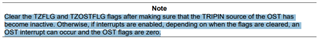
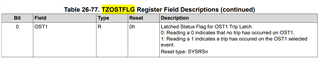
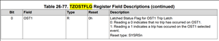
Within the interrupt, we are monitoring the OST1 bit of the PWM1_TZOSTFLG register, but occasionally this bit does not go High.
However, the INT and OST bits of the PWM1_TZFLG register do go High, causing only the trip to occur without anomaly detection.
At this time, none of the other bits in the PWM1_TZOSTFLG register are set, and the entire register is zero.
Could you please explain why the OST bit of the TZFLG is set, but the TZOSTFLG does not go High?
Best Regards,
Ito