This thread has been locked.

If you have a related question, please click the "Ask a related question" button in the top right corner. The newly created question will be automatically linked to this question.

LAUNCHXL-F280039C: CanFd bus off

Part Number: LAUNCHXL-F280039C

Tool/software:

Hi team,

There was a problem when debugging canfd sends

  1. debugging:

Demo board : LAUNCHXL-F280039c

Use the routine mcan ex9 transmit.c.Do not change the configuration of mcan in the routine.Nominal Bit Rate of 500 kbps and Data bit rate of 1 Mbps is used.

Modify the sending program to send a frame of data at an interval of 1s.

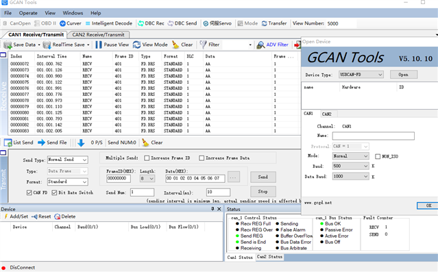
After sending dozens of data, canfd entered the bus off state because MCAN_ECR.TEC >255.

When I set brs=0,Nominal Bit Rate of 1 Mbps and Data bit rate of 1 Mbps is used. canfd can operate normally even if one frame of data is sent at 1ms interval 

At first, I suspected that there was an anomaly in the canfd_rx self-test due to the receive delay. 

But I calculated, canfd_rx self-test should not be a problem

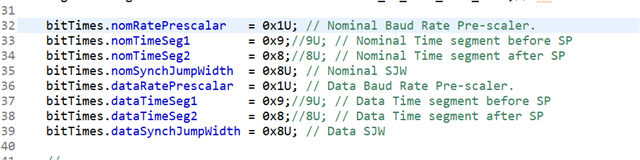
The theoretical sampling points can be calculated according to the sampling point setting

Nominal SP = (bitTimes.nomTimeSeg1 + 1)/(bitTimes.nomTimeSeg2 + 1 + bitTimes.nomTimeSeg1 + 1) = (9 + 1)/(9 + 1 + 8 + 1) = 10/19 ≈ 52.6%

Data SP ≈ 52.6%

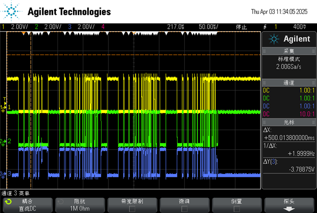
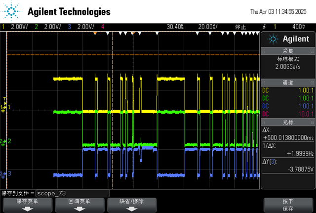
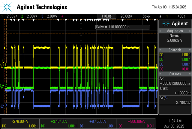
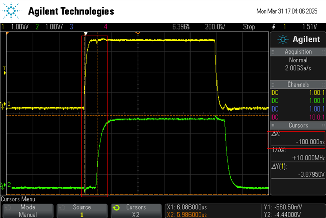
The oscilloscope captures the bus delay time about 100ns, yellow -> canfd_tx , green->canfd_rx

When set brs=1, 

Nominal Bit Rate of 500 kbps,1 bit time = 2000ns, So Nominal SP should be at 2000ns * 0.526 - 100ns =952ns

Data bit rate of 1 Mbps, 1bit time = 1000ns, So Data SP should be at 1000ns * 0.526 - 100ns = 426ns

From the data, there should be no send data error count

So this is where I don't quite understand, why does the bus off state appear after brs is enabled

2.Question

I'm not sure if my calculation is correct, if not, can you explain it.

why does the bus off state appear after brs is enabled? Is there any way to solve this problem, can you help debug it?

Thanks!

  • Hi,

    Could you check the contents of MCAN_ECR register to see which errors are accumulating before CAN bus goes into bus off condition?  I have not encountered any bus off condition when using mcan_ex9_transmit example (with brs=1; 500Kbps NOM; 1 Mbps data - original test settings) when using PCAN to receive data from the F280039 LaunchPad.

    Regards,

    Joseph

  • Hi Joseph,

    This is the information in the ECR register, and the TEC register is almost filled

        //
        // Configure the MCAN Module.
        //
        MCANConfig();
    
        while(1)
        {
            //
            // Write message to Message RAM.
            //
            MCAN_writeMsgRam(MCANA_DRIVER_BASE, MCAN_MEM_TYPE_BUF, loopCnt,
                             &txMsg[loopCnt]);
    
            //
            // Add transmission request for Tx buffer 0
            //
            HWREG(MCANA_DRIVER_BASE + MCAN_TXBAR) = 0x00000001;
    
            //
            // Wait till the frame is successfully transmitted (and ACKnowledged)
            // "Tx Buffer Transmission Occurred" register is polled.
    
            while(HWREG(MCANA_DRIVER_BASE + MCAN_TXBTO) == 0x00000000)
            {
            }
    
            DEVICE_DELAY_US(1000000);
    //        //
    //        // Stop Application.
    //        //
    //        asm("   ESTOP0");
        }

    Change the single send from the example to send every 1s

    After the PC tool receives dozens of data, Canfd enters the bus off state

  • Hi,

    The incrementing error is TEC which is during transmission.  This counter increments if there is a transmission error and transmission error occurs if there is no ACK sent by any receiving node.  With BRS=0, your receiving node (GCAN) is able to receive all data without errors, meaning that GCAN is able to send back ACK for all the frames sent at 1Mbps NOM and data rate.  Can you check on your GCAN settings to ensure that with BRS=1, NOM bit setting is 500Kbps and data rate is also 1Mbps?  This should be consistent with the MCAN settings on the Launchpad otherwise GCAN may not be able to send an ACK signal for a sent frame with NOM rate of 500Kbps and data rate of 1Mbps.

    Regards,

    Joseph 

  • Hi Joseph

    Do you mean that the TEC count may have increased due to the inability of the GCan tool to reply ACK bits for each frame?

    Due to the imperfect function of GCan tool, it cannot display the error frame information in Canfd mode, so I grabbed some error frame data waveforms

    data lenth = 1;

    data[0] = 0x01;

    txMsg[loopCnt].mm       = 0x81U;

    yellow:CAN-RX;

    green:CAN-TX;

    blue:CANL-H;

    In this image, it took the fourth send to succeed

    The waveform is expanded as follows:

    first frame:

    second,thridly frame

    Fourth frame

    The first frame seem to be a data frame error or crc?

    The second、thridly frameframe seem to be last few bits error,is ACK or other?

    The fourth frame is the complete correct frame

  • Hi,

    It is kind of hard to identify the parts of the frame on the scope shot.  Not sure if the scope you are using has the ability to decode CAN frames.  Most of the scopes have this ability and this is capability useful in identifying errors.  See example scope shots used in app note SPRACE5 .  There is also an example showing how ACK works.  Frame illustrations in the app note is for DCAN but it is applicable to CAN-FD.  There are subtle differences in the control field but rest are same.  It would be good if you can use the scope's capability to decode the CAN frame.

    Regards,

    Joseph