This thread has been locked.

If you have a related question, please click the "Ask a related question" button in the top right corner. The newly created question will be automatically linked to this question.

TMS320F280039C: for the PMP23338

Part Number: TMS320F280039C
Other Parts Discussed in Thread: PMP23338

Tool/software:

Hello everyone!
I am currently researching PMP23338, and I have a few questions would like to ask you for advice:
Q1. The routine indicates: A-TASKS(executed in every 1ms), B-TASKS(executed in every 5ms). Through testing, it was found that: the local A-TASKs executed in about 10ms), B-TASKs executed in about 300ms). My understanding is that when using my own architecture to load the corresponding when performing tasks, which should be loaded strictly according to the specified time sequence(1ms/5ms),right?

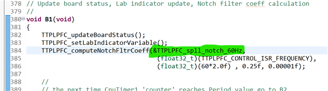
Q2. About the TTPLPFC_computeNuchFltrCoeff(), why is it not included in the initialization calculation, but we need to arrange for repeated calculations in the loop. It have any special considerations?

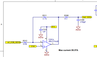
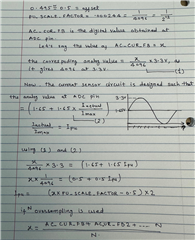
Q3. Why is * -2.0f required for TTPLPFC_read_cReturnCurrent() to read current?

Q4. Why is it necessary to perform an absolute value operation on duty( fabsf(duyt) ) in TTPLPFC_HAL_updatePWM()? Based on what considerations?

Q5. In Pre defined Symbols:
F28x_DEVICE
CPU1
LARGE_MODEL
BUILD-F28003X
What are the functions of these definitions? Additionally,
where is "__TI-EABI__ "defined (not found) and what is its specific function?

  • Hello Milo,

    Q1. Yes, these tasks are performed in given time, but if performed computation in either ISR or in this timing tasks takes longer than timer, it will take multiple instance of ISR/Timer Tasks to complete the calculation. You can profile the piece of code to determine which part is taking longer. ISR will meet timing requirement only if code execution is finished in less timing than ISR period.

    Q2. Highlighted structure uses 2p2z compensator in which x1 and x2 intermediate data is updated regularly that's why it has to be in repeated calculation.

    Q3. * -2.0f is current scaling specific to pmp23338 board so that code can be used on other HW platform by removing this factor. You can choose your own scaling as per the HW.

    Q4. In this reference design, AC current polarity is changed using low frequency leg switching, along with that high frequency high/low side FETs also change their role from activeFET to syncFET and syncFET to activeFET. In this scenario, high frequency leg is operated as synchronous boost converter based PFC. That is why we need absolute value of duty ratio even if control effort can produce both positive and negative value.

    Q5. The predefined symbol will let compiler know what device it is compiling for which section/piece of code. Pre-defines are just for enabling / disabling certain code throughout your project. You can find some explaination here on other e2e for example large model: https://e2e.ti.com/support/microcontrollers/c2000-microcontrollers-group/c2000/f/c2000-microcontrollers-forum/1317482/tms320f28035-large_model-pre-defined-in-c2000ware-example-code

    For the detail on "__TI-EABI__" you can refer: https://software-dl.ti.com/ccs/esd/documents/C2000_c28x_migration_from_coff_to_eabi.html

    For all other symbols, you can refer specifics by searching those in C2000 Compiler guide: https://www.ti.com/lit/ug/spru514w/spru514w.pdf

    Regards,

    Sumit

  • Hi Sumit,

    Thanks for your kind reply.

    Q3:Has there been any update to the hardware solution compared to the picture I attached? I still don't quite understand why we need to multiply by -2.

    Q4: Agree with you about" high frequency high/low side FETs also change their role".However, imagine a situation where the duty cycle calculated for a certain cycle is negative(assumed the period within the positive half-cycle that there is no AC current alternating). After taking the absolute value, doesn't it mean that positive feedback has been introduced into the original system? Could you further explain it?

    Best Regards,

    Milo

  • Milo,

    Q3. Please find the following explanation for factor -2.0f specific to the circuitry. Let me know if any issue understanding the same.

    Q4. In this case, low frequency FET changes their role as well depending on positive and negative AC cycle, so that HF boost converter leg sees it a like in terms of control whether its positive or negative. Imagine HF leg operating like normal boost converter irrespective of AC cycle polarity. That's why we keep only magnitude of this variable TTPLPFC_dutyPU passed in "duty" variable in TTPLPFC_HAL_updatePWM(uint32_t base1, uint32_t base2, float32_t duty, float32_t phase1ScaleFactor). This absolute duty is applied updated PWM and not used in control calculation and duty can not be negative in this case.

    Regards,

    Sumit


  • Hi Sumit,

    Q3: How to understand that the resistance values of R311 and R312 are different, but it does not affect the corresponding proportion?

    Q4: Let's limit the discussion to the positive half cycle, the polarity of the alternating current in the low-frequency FET does not change. Consider an incremental PI control loop. When the calculation result of the current cycle is negative, it means the value of D will decrease in the next cycle. However, if you take the absolute value, it will only create positive feedback (a control effect we do not want). Is this way of thinking not applicable in position PI control? Still don't quite understand the statement "only focus on the magnitude of D but not its sign." Moreover, why do we deliberately distinguish between positive and negative values of D in the TTPLPFC_pwmDriver() function? This seems contradictory.

    Best Regards,

    Milo

  • Milo,

    Q3: So our calculation inside this example are mapped with full scale of the ADC number. In this case, TTPLPFC_I_MAX_SENSE decides full scale of current with corresponding 3.3V range that is associated with number "4096" full scale of ADC. This way you can decide gain value "1+(R311/R312)" for taking advantage of full scale.

    Q4: In this example, TTPLPFC_HAL_updatePWM() is only used for updating CMP value which is corresponding to duty of the ePWM and not for running compensator to do any control loop. This compensator run happens in earlier function "TTPLPFC_runCurrentLoop();" So there won't be any positive feedback. In any case of control, duty that we need to apply can not be negative because that's not possible. Please refer to the following video training series on TPPFC especially part 2 to understand block diagram of how this is implemented: https://www.ti.com/video/series/digitally-controlled-high-efficiency-and-high-power-density-pfc-.html

    Let me know if this makes sense.

    Regards,

    Sumit