This thread has been locked.

If you have a related question, please click the "Ask a related question" button in the top right corner. The newly created question will be automatically linked to this question.

TMS320F28P650DK: Problems connecting to device after programming

Part Number: TMS320F28P650DK

Tool/software:

Dear Forum,

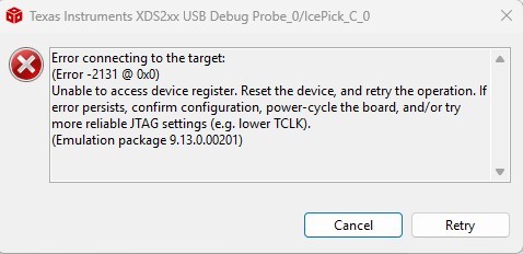
I have developed some custom digital control boards based around the TMS320F28P650DK9ZEJ part. The prototype board I have been using for a few months has been working well but I'm not able to connect to it via the XDS200 now. I receive an -2131 error as shown below:-

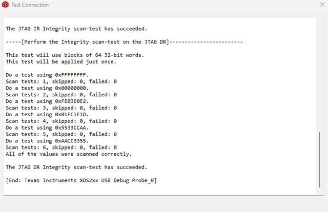
I can't even connect to the board using the 'test connection' tool under the new configuration tool. The C2000 part is hosted on a small daughter board so I built another one and powered it up separately from the main system. I was able to connect to the device straightaway and upload my test code. However, on that new board now I can no longer connect to the C2000 part.

Any idea on why this might happen? I do have another spare controller board but am reluctant to program until I know what is happening here. Just a reminder, the first board was working without issue for months just prior to this issue.

Thanks,

Iain

  • Also, interestingly, if I hold the TMS320F28P650DK in reset (hold the nXRS pin low), I am able to connect to the part using the 'test connection' function:-

    So I think the XDS200 is working fine?

  • Hi Iain,

    That is interesting. What was the state of the device when you're failing to connect? Is it executing a program in the flash?

    Best,

    Matt

  • I'll also add that we have debug steps for a 2131 error code in the C2000 MCU JTAG Connectivity Debug Guide:

    However, since this involves a custom board, the nature of the issue may be more complex. This is a good place to start.

    Best,

    Matt

  • Thanks Matt, I’ll take a look at this.

  • Hi Matt, yes the part is executing code from flash. On the new board, the sequence of events was (1) check connection using the target configuration check - works fine. Then (2) program the flash which it did successfully. Then (3) cycle power to the board. The MCU powers up and executes code but from that point I can’t connect in anyway to the MCU. I have ordered a spare XDS200 now to rule out damage from the one I have presently. Have you seen an XDS200 ever brick a device?

  • Hi Matt, ok I made some progress. Being a hardware engineer I decided to take a look at the status of the JTAG pins when the XDS200 is trying to connect. In the scope plot below, C1 (Yellow) is TMS, C2 (Red) is TDI, C3 (Blue) is TDO and C4 (Green) is TCK. 

    This is the first activity on the JTAG port when I try to connect with the target configuration tool. We get activity on TCK and TDI but nothing on TMS or TDO. I'm not sure if this is expected or not but I read the guide you included and noticed that there is an ability to connect to this part using only two pin JTAG:-

    I changed to the cJTAG (1149.7) 2-pin advanced mode with the setting as shown above and..... this allows me to connect to the device, program flash and read debug values. 

    I went down this route out of curiosity and after seeing some of the JTAG signals not being active with the normal four wire approach. The questions I have are:-

    1) Any idea what might be causing this? The board has been happily running with the default four wire JTAG for months and I don't use any of the GPIO's which are multiplexed with the JTAG pins

    2) Is this an acceptable way to program the device? I've never used it before and only stumbled on it by a bit of luck.

    Thanks,

    Iain

  • OK< I know what is going on now. Sorry to have wasted your time but in error, I had assigned pin T12 to be UART_B without checking that this is also the pin which is used for the UART TDI function. So, when I programmed the device and code execution began, TDI was no longer available for comms when I tried to program/connect again. Luckily the 2-wire cJTAG mode still worked and I was able to connect again. I have moved back to the normal four wire JTAG mode now and returned pin T12 to be just TDI function.

  • Hi Iain,

    I'm happy you were able to resolve the issue so fast! Thank you for updating the thread with a detailed explanation of the resolution.

    2) Is this an acceptable way to program the device? I've never used it before and only stumbled on it by a bit of luck.

    cJTAG (IEEE 1149.7) is an extension to the JTAG standard (IEEE 1149.1), that reduces the number of required pins by multiplexing the TMS, TDI and TDO signals on a single bi-directional pin (which is why you were able to connect with cJTAG, but not normal JTAG), providing all the normal JTAG debug and test functionality.

    Please take a look at these threads for more info on cJTAG:

    https://e2e.ti.com/support/microcontrollers/c2000-microcontrollers-group/c2000/f/c2000-microcontrollers-forum/754473/tms320f280049-question-jtag-vs-cjtag

    https://e2e.ti.com/support/microcontrollers/c2000-microcontrollers-group/c2000/f/c2000-microcontrollers-forum/807783/tms320f280049-cjtag-vs-jtag-speed-robustness

    Best,

    Matt