


Part Number: TMS320F28335
Other Parts Discussed in Thread: C2000WARE
Tool/software:
I'm using TMS320F28335 on an evaluation board. I'm having this issue when I want to read the amplitude of 5Vrms voltage on ADCA0 of the dsp I'm not getting a sine wave, I'm getting this wave which is not a sine wave as shown below.
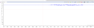
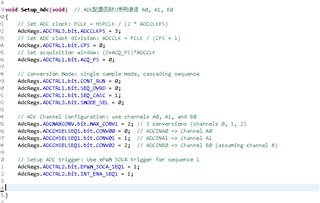
I'm new to using this dsp and i haven't figured out the issue . my settings for the ADC are as shown below
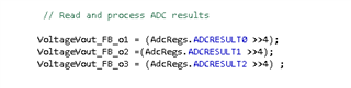
In the main function I read and process my ADC as shown below.
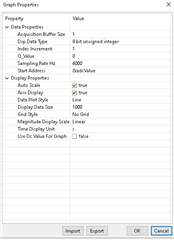
The above are my settings on the graphs properties. Any help i would appreciate it.
